
March 2019
Antenna Tracking Ground Station

I had been wanting an antenna tracker for quite a while and when I came across this project, I knew I had to have a go.
A normal (if there is such a thing) antenna tracker works by calculating the angle between the known position of the ground station and the GPS location of the plane, the problems with this solution are that you need to send the GPS information from the plane to the ground station (usually over the audio channel of the video signal that you are trying to track), and then do some (probably) rather complex maths to work out where to point the antenna. It also means that each plane that you want to track has to have the equipment to send the GPS data to the ground station. Considering even at the moment I own 4 planes that I want to be able to track, it can very quickly get expensive. There are many problems with this and I just don’t like it.
The ‘super simple RSSI antenna tracker’ project started by andreiva instead simply uses the difference in received signal strength of two antennas that are pointed slightly apart from each other, where it moves the servo towards the antenna with a higher signal strength. The project hadn’t been worked on in over 2 years and since then the technology around 5.8GHz video receiver has moved on significantly, so I would need to make some changes to allow me to use it with new equipment. He also only had his antenna tracker moving one axis and, in the future, I will really need 2 axis of movement for my antenna tracker. Furthermore, he uses a servo to drive his antenna tracker, this is ok, but they can only rotate 180 degrees at most and, when moving such a large weight, don’t centre very accurately. Instead I wanted to switch to using geared stepper motors, which would allow me to have an infinite amount of rotation and I would still always know where the antenna is pointed (compared to just using a motor with a gearbox, where you would only know its relative position).
Version 1.0 was designed to be a stop-gap measure until I had time to design a pan and tilt head using stepper motors to drive the axis instead of servo motors, because I realised that although I knew how to write the code for the tracking algorithm, and the code to drive servos, I had never before tried to drive a stepper motor. This would mean that I would need to do lots of research, potentially buy lots of hardware and then learn how to control it with an Arduino (or another microprocessor).
My solution was to just make some small modifications to andreiva’s code to allow it to work with the new 5.8GHz receivers that I am using. Other than that, for now all of the code is taken directly from andreivas’s project.
For version 2.0 I’ll be rewriting the code completely and using stepper motors to drive the antenna tracker. I will also be switching to a two-axis system and attempting to use a more intelligent tracking algorithm, rather than just ‘go towards highest strength’.
Using RSSI as a tracking method does have some problems though, the most prevalent being that RSSI (Received Signal Strength Indicator) only tells the microprocessor how much RF energy it is receiving, not how much of that is actually the signal it is looking for. This means that is there is a source of interference the antenna tracker can lock onto, and track, that instead. It will also generally be less accurate than a GPS based tracker, because the tracker never knows exactly where the plane is.

3d printed panning plate with one diversity 5.8GHz receiver fixed on it.
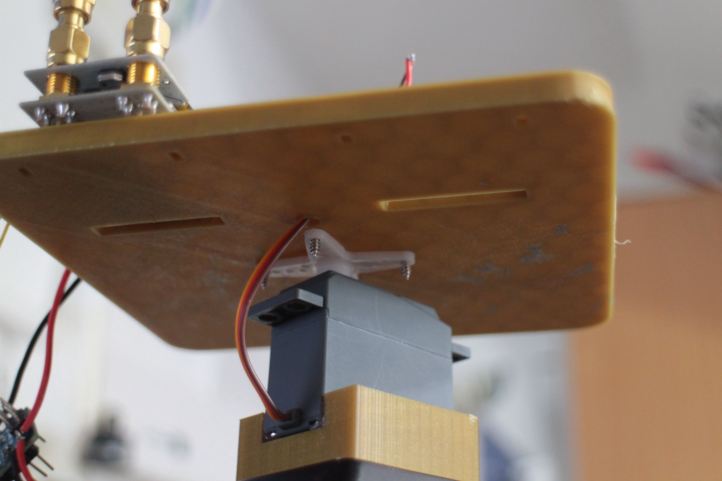
The servo used to drive the pan plate.
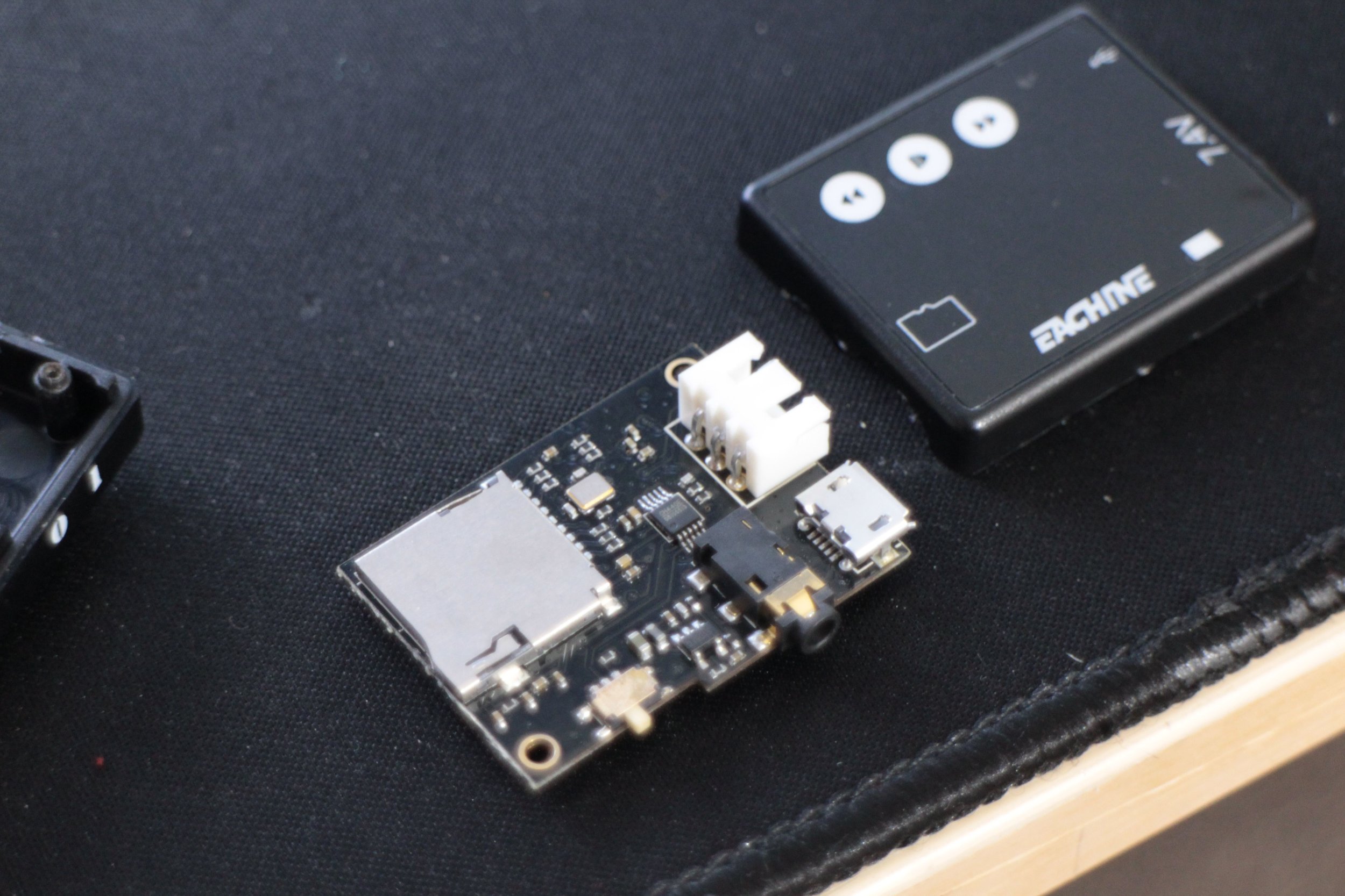
Disassembling the DVR that I want to use to record the video downlink. I’m having to take it apart because it uses a 2.5mm jack for video input as standard, which I’m not particularly happy with. Its loose causing it to occasionally lose connection.
Instead I will just be direct soldering to the pads.
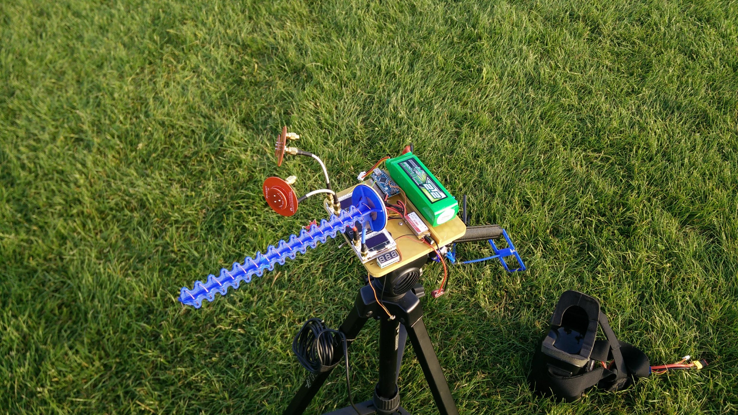
The completed antenna tracker. The two red patch antennas on the left are the antennas used for tracking, and the blue helical antenna on the right is the antenna used for receiving the video signal.
June 2019 update -
I have been using the antenna tracker for over 2 months now and have found it to work very well, it’s nice and convinient to setup and tracks the plane very well, there’s not really too much to ask for from an antenna tracker.
I do still want to build a version 2.0, but it may be able to wait a while longer.