
November 2018
Customing a Radio For My Needs
For nearly a decade I have been using a Spektrum DX7S Transmitter to pilot my planes, overall, I have found it to work adequately, but now I am wanting to start on a project that will require long range radio equipment and preferably more customisable ‘mixes’. I felt that it was time to upgrade.
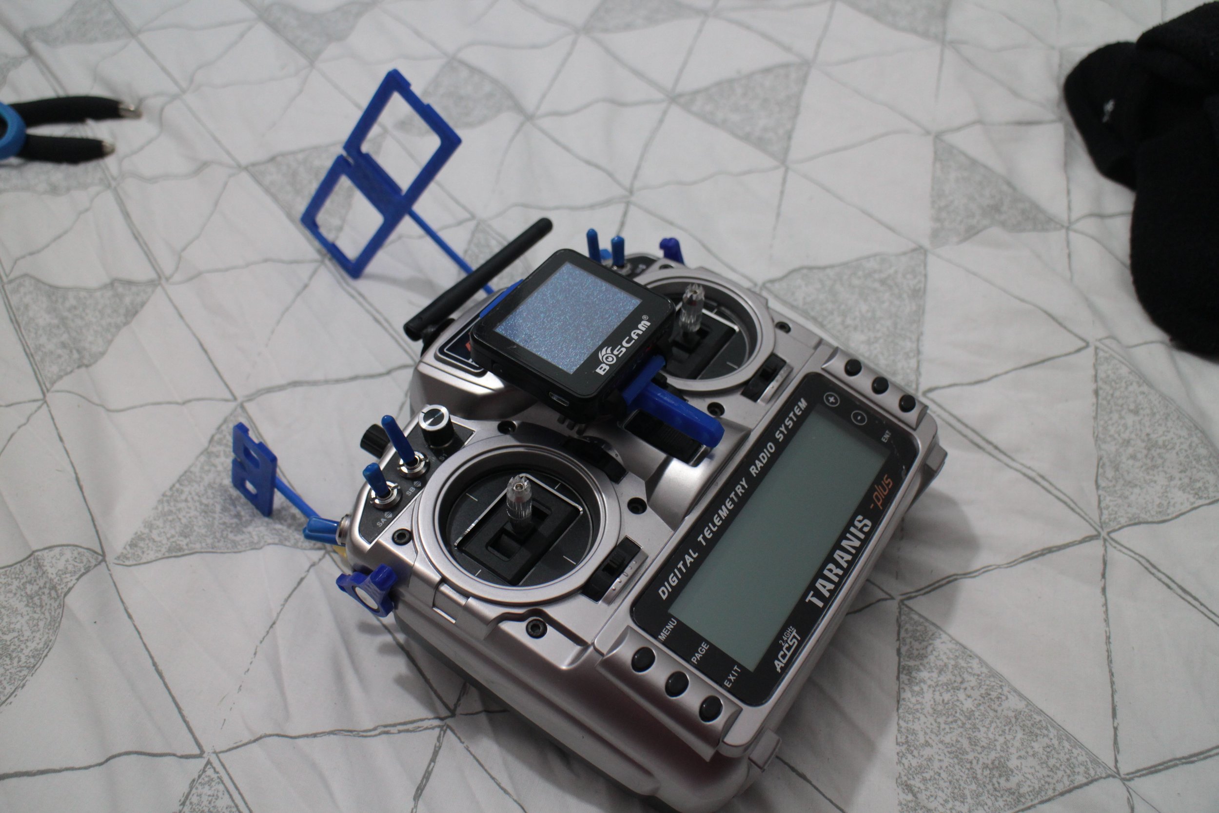
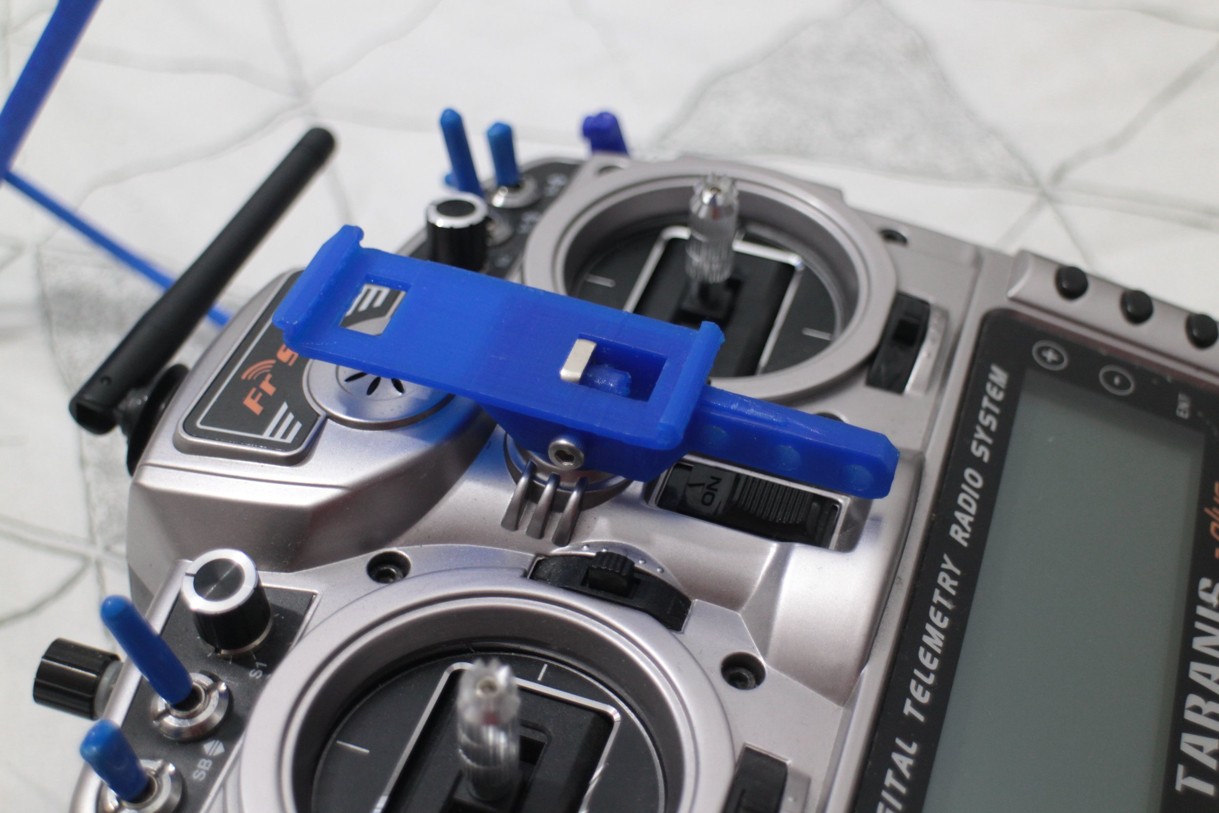
The obvious choice of upgrade was the Taranis X9D Plus from FrSky, it’s become the staple of most FPV pilots and ‘makers’ due to its extremely customisable software that is fully open source and because as standard it has a very long range for a 2.4GHz transmitter of over 2 miles. The only problem with this is that I now have lots of DSMX and DSM2 protocol receivers that are only compatible with Spektrum transmitters. Normally this wouldn’t be a problem as you can buy a module to go in the module bay of the Taranis, however, I will need to be use that module bay for an even longer range 868MHz transmitting module.
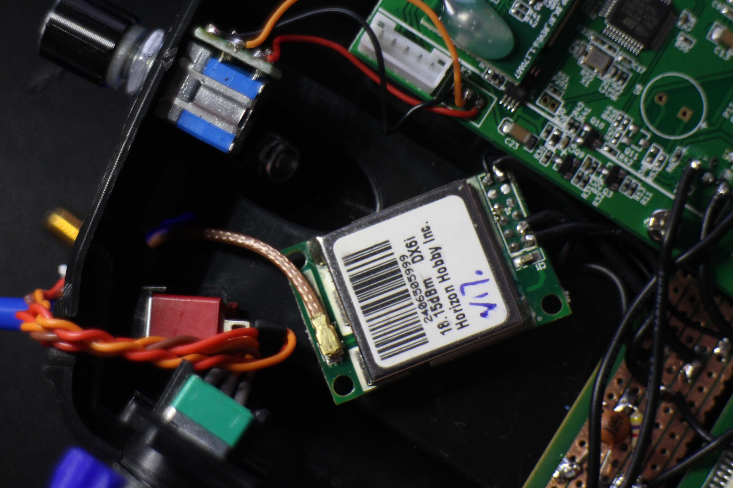
Therefore, my idea was to have three transmitting modules built into the transmitter, the standard 2.4GHz ACCST module that is built onto the main circuit board of the transmitter, the 868MHz FrSky R9 module that plugs into the module bay and then take the 2.4GHz DSMX/DSM2 out of my old DX7S and put that inside the new transmitter with a physical switch to switch between the R9 and DSMX/DSM2 modules.
Part of the work had already been done for me as taking the module out of old Spektrum transmitters and using them in the module bay is well documented and the code has already been integrated into the transmitters software to be able to ‘speak’ to these modules. This means that I only need to find a way to mount the new transmitting module inside the radio and a way to switch between the two - in theory.
I decided that if I was going to go to the effort of doing this, then I would do all the other mods that I would want to do to the transmitter as well, this included a Lithium Ion battery, a better antenna mount and handle, a third joystick on the back of the transmitter (to control a pan and tilt camera mechanism), a mount for an ‘FPV Watch’ screen and an integrated wireless trainer function.

First off was the Lithium Ion battery mod, I decided to use two lithium cells in series to roughly match the voltage range of the 6 NIMH cells the transmitter comes with. I chose NCR18650B’s because they use the increasingly common 18650 form factor and because they have a high volumetric energy density of 675 Wh/L compared to around 450 Wh/L for a standard lithium polymer soft cell battery or a NIMH cell with as low as 200 Wh/L.

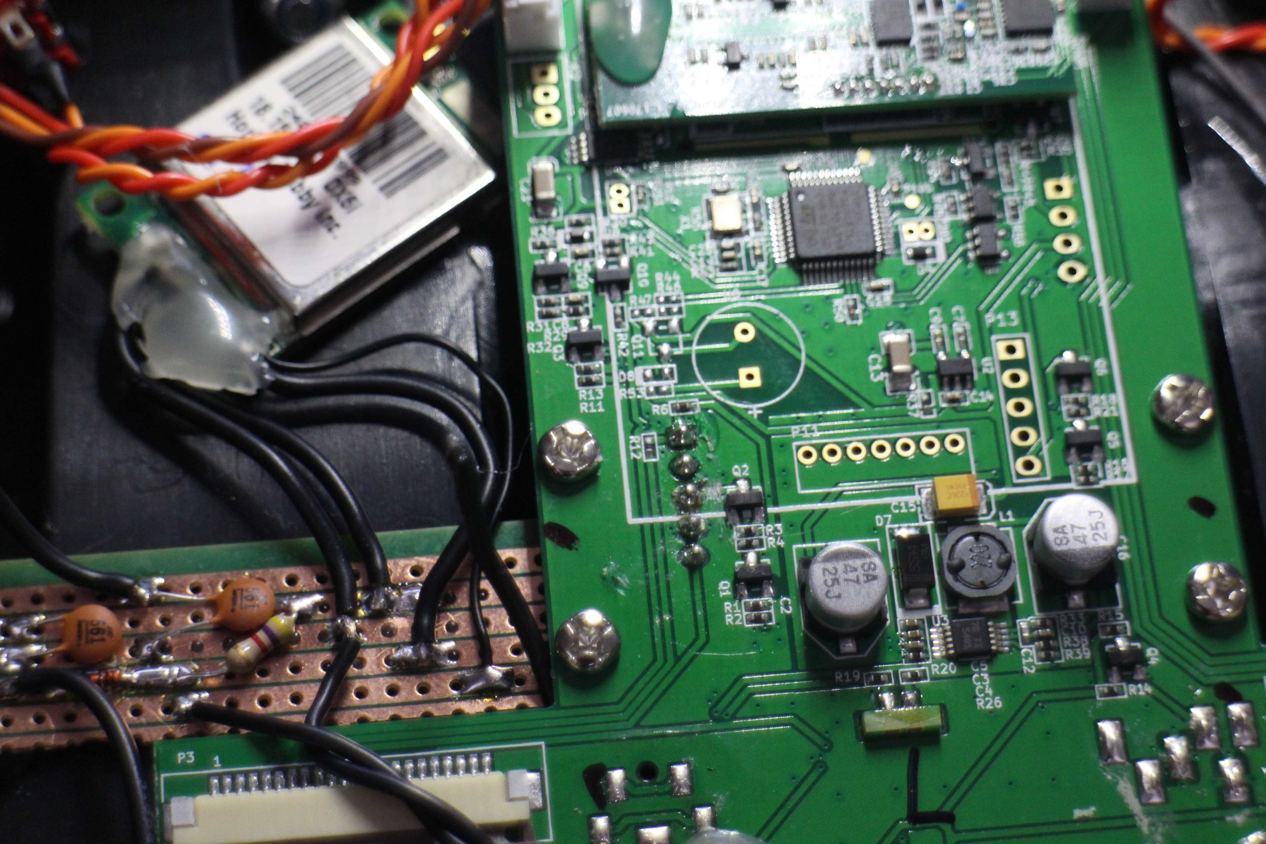
I connected up the new module to backs of the pins that extend out into the module bay. I then cut the trace between the Q2 mosfet and the V+ pin that goes to the module bay so that I could insert a switch between them, so switch between powering the module bay (and therefore the long range R9 system) and the internal DSMX/DSM2 module
I next found a suitable place for the new transmitting module in the transmitter and drilled a hole in the case of the transmitter for the antenna extension cable to exit the transmitter. and then I glued it down with hot glue - since it should never heat up too much.
I added a power distribution board (made from perf board) to step down the 5V from the Taranis to the 3.3V needed for the module (both supply and logic levels) roughly according to the diagram below that I found at : www.flitetest.com/articles/spektrofy-your-taranis

Wiring Diagram : www.flitetest.com/articles/spektrofy-your-taranis
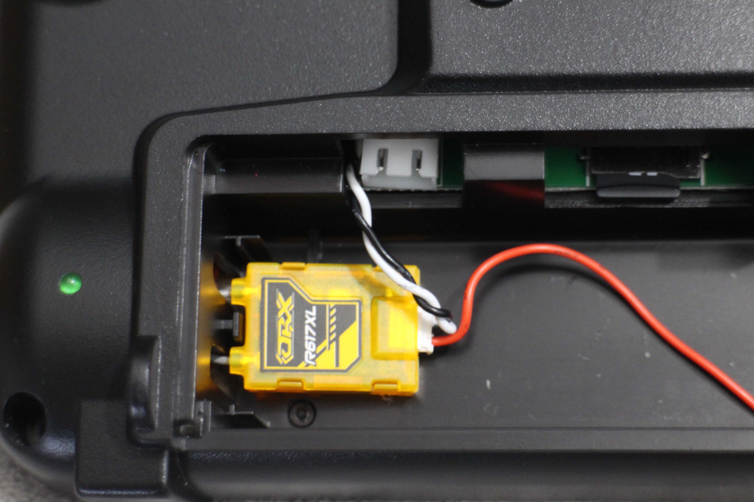
I installed the receiver for the wireless trainer system in the battery bay.

The CAD model for the new battery bay door, This part will allow me to mount switches on the back of the transmitter and allow for the new form factor of the new 18650 batteries.
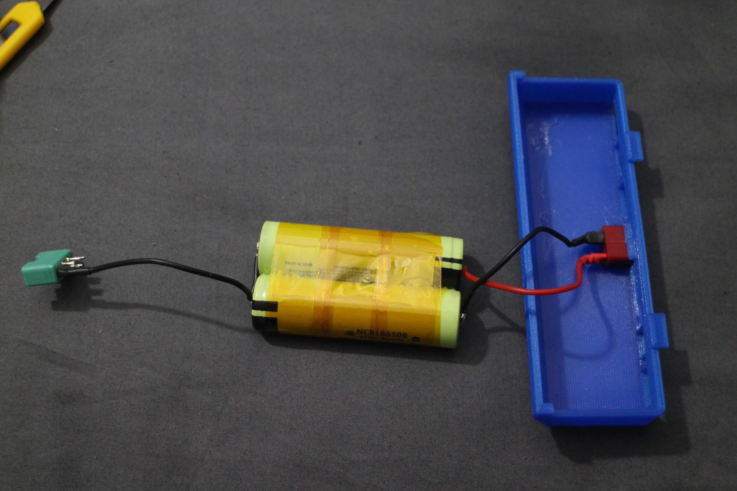
The 3D Printed battery door with the battery

This connector is used to balance the voltage of the 18650 cells and to connect to the 3rd joystick which will be mounted of the back of the transmitter
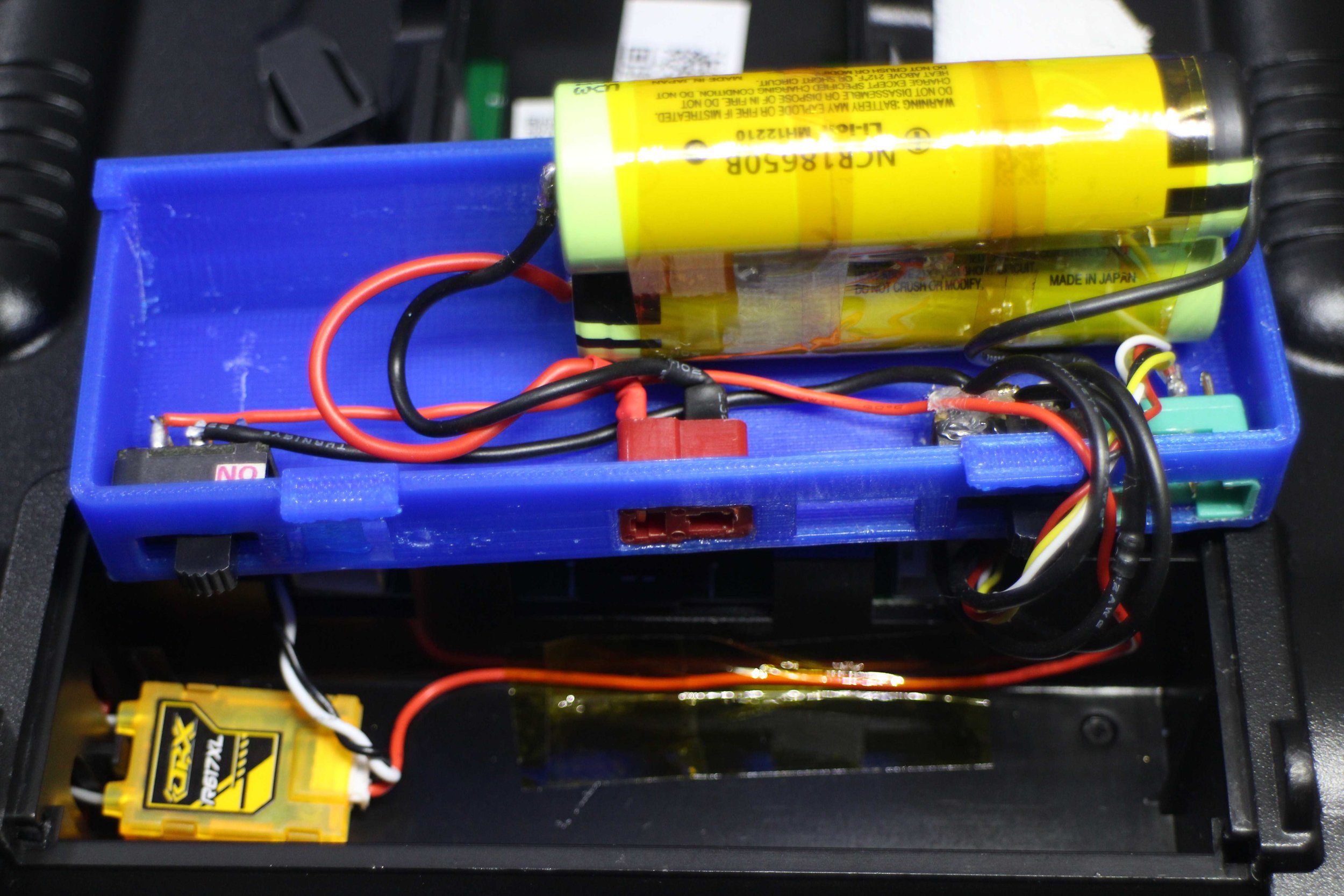
Battery glued into the battery bay and the switches for the transmitting modules (right) and the receiver for the wireless trainer (left) installed
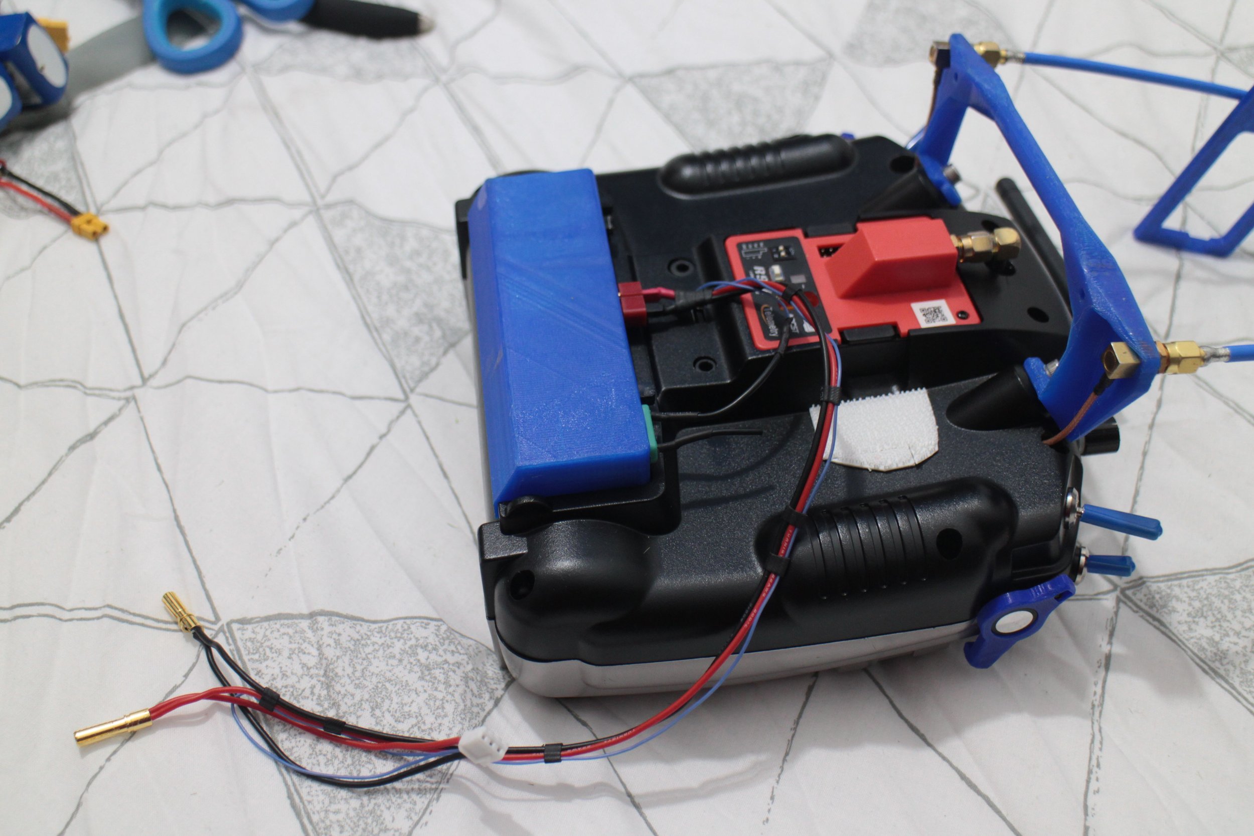
The battery bay on the back of the transmitter with the charge leads connected.
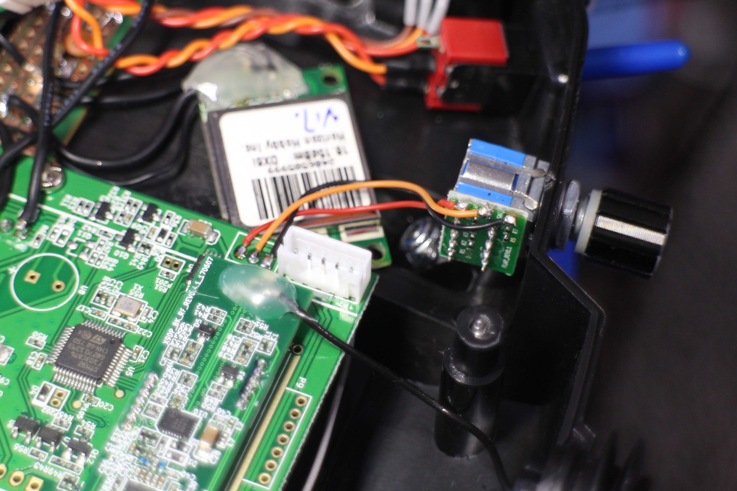
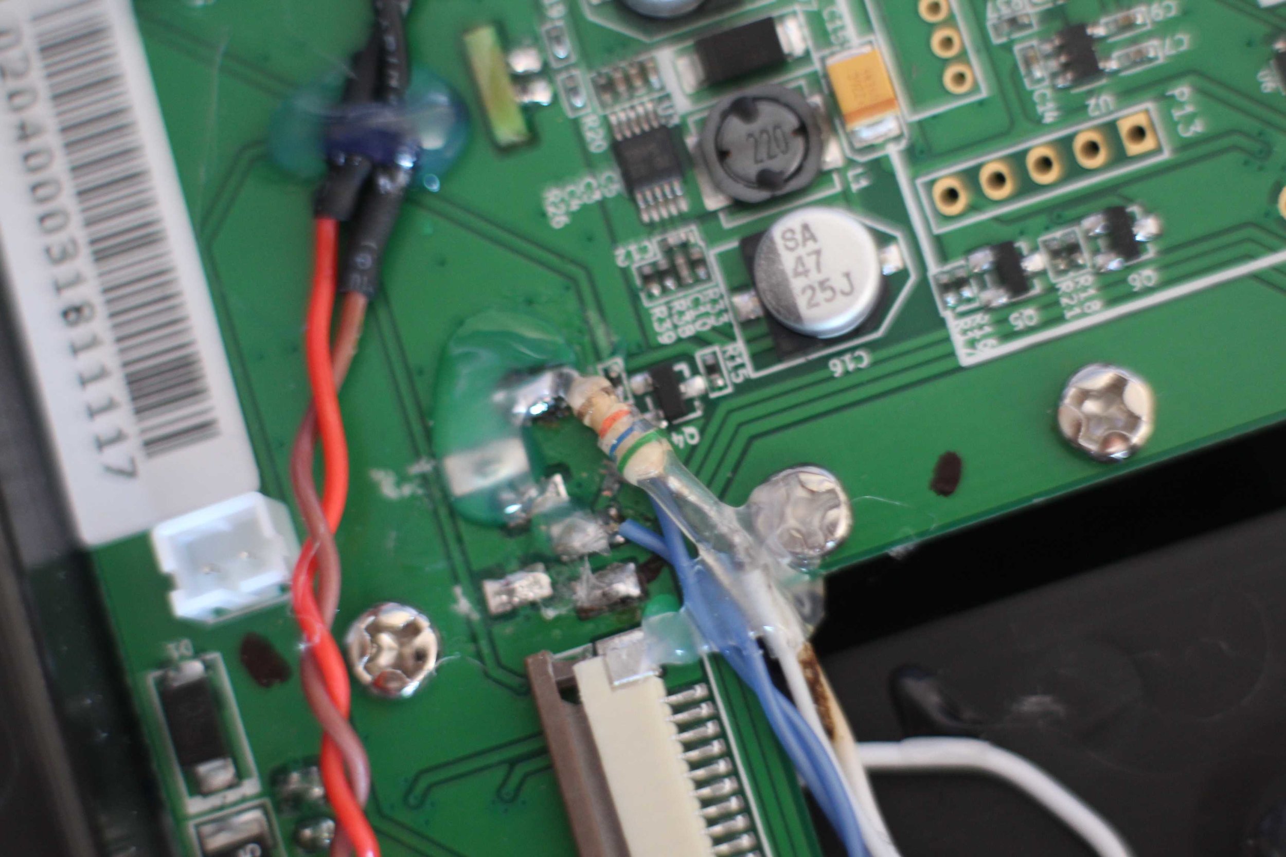
Midway through the mod I found three unused pads on the mainboard of the transmitter. At first, I thought they were diagnostic pads, but there placement and silk screening seemed to suggest they were for a 3 position switch. After some research I found they were for a potentiometer input that was never used from the factory. I decided to install a 6-position rotary switch which emulates a potentiometer with a resistor array. This is to make it easier to use for changing autopilot modes.

The wires for the new joystick spliced into the wires for the potentiometers mounted on the front of the transmitter. I rarely use the front potentiometers, and having the joystick in parallel with them will mean that I will be able to use them as ‘trims’ when using the joystick and I will be able to control the pan and tilt with the potentiometers when not using the joystick.

The green multiplex 6-pin connector is used to bridge the two halves of the case

The third joystick mounted on the back of the transmitter with 3M Duallock so that it can easily be removed when not needed.

The CAD design for the new handle with integrated antenna mounts.


The back half of the case, particularly showing how I’m routing the antenna coax through the case.
The 7 pads shown here all go to a standard 2 channel + ground 3.5mm jack socket, I found that the other 2 of the other 4 pins are a normally closed indicator for when a jack is in the jack socket with the other 2 of the 4 being the same but normally open. It turns out that the transmitter will not enable trainer mode unless the first 2 pins are open (jack plugged in). So to bypass this I cut the trace between this switch and the ‘sense trace’ going to the mainboard on the transmitter and instead connected it to the second pole of the double pole switch that I am using to power the wireless trainer receiver.
Unfortunately, this now introduces another problem, because now to use the standard wired trainer port I would have to have the wireless receiver powered as well to activate the trainer port. This could cause interference in the signal going to the transmitter. To get around this I just used a 10k resistor between the wireless trainer system receiver and the transmitter mainboard, this is not a perfect solution, but in practice allows the signal from the wireless receiver to be negligible compared to the wired port when they are both in use

32awg jumper wire soldered onto a 0402 resistor and better view of the cut trace.

Red wire soldered to the source of power I found that is only on when the transmitter is powered on. This means I can’t accidentally drain the transmitter battery with the wireless trainer system.

CAD model of the screen mount for the front of the transmitter

A ‘hardwired’ power source for my long range module that I can use for higher risk flights when I don’t want to trust the funny buisness going on inside the transmitter, not that I’ve been given any reason not to trust it yet.
Screen mount attached to the transmitter.

The Finished unit
June 2019 update -
The transmitter has worked very well for just about everything I have wanted it to and has been perfectly reliable despite my many modifications. It has been very useful having 3 transmitter modules in 1 transmitter and the switchover is almost completely seamless. Having the two lithium cells has also been a nice addition meaning that I have only had to charge the transmitter twice, despite daily use over the last 6 months.
I want to redesign the screen mount to move it just a bit further away from the sticks to give my thumbs more breathing room at the extremities of stick movement and I want to swap out the 6-position switch for two 2-position switches that will be mounted on the top of the radio, since it turns out that the 6-position rotary switch has too many positions to really be useable.