
April 2019
Long Range FPV Plane V1.5

Goals For FPV Plane V1.5
The only part of the plane that I will be rebuilding for version 1.5 will be the wing, since that is all that was broken of version 1.0. So, the plan for V1.5 is to rebuild the wing with some new improvements and then continue developing the plane as planned.
The main problems of V1.0 that I want to address with V1.5 are the spar pressure points, the torsional rigidity of the wing, the weight of the wing and the unintended under camber of the inside sections of the V1.0 wing.
I’m going to address the spar pressure points that were created by the 3d printed wing ribs, by using three spars instead of one. Two of these will be 6-5mm pultruded carbon tubes, and the other will be an 8-6mm roll wrapped carbon tube. This main 8mm carbon tube will be much more resistant to the pressure points created by the 3d printed wing ribs compared to the 8-7mm pultruded carbon tube used in the V1.0 wing because roll wrapped carbon tubes have significantly more crush resistance. The 6-5mm tubes will be 200 and 400mm long, hopefully giving the wing a good ‘strength distribution’ across the wingspan. Extending the main 8mm carbon tube to 1000mm will also allow me to switch from using a 6mm solid glass fibre rods in the outer wing sections which were very heavy (20g a side) to using 6mm spruce wood spars. The spruce wood spars will be less strong but since they have less leverage acting on them it should be fine.
Overall this spar solution will weigh only 5g more than the old spar solution but should be significantly stronger. I hope that I will never have to test it to destruction, but I presume it will be somewhere in the range of 1.5-2.0 x stronger than the old wing (in terms of positive G’s that the plane will be able to pull before snapping).
The other advantage of this new spar solution is that it will now be contributing to the torsional rigidity of the wing, whereas the old spar was very flexible torsionally, and it was instead designed to rely on the wing skin alone for torsional strength. Hopefully this will allow me to remove most of the glass fibre tape that I used on the old wing. This could potentially save me up to 60g.
The other big change that I want to make is adding flaps to the inner sections of the wing. The reason I didn’t do this originally was to save weight and add simplicity, unfortunately, I didn’t realise at the time that if I didn’t have flaps, because of my building technique my inner wing sections would have a natural under camber that I couldn’t prevent. This isn’t too bad, but the Airfoil will be more efficient without it and if I add flaps I will be able to land even slower.

The new wing ribs and motor mounts.

Wing ribs glued to the carbon with 2-part epoxy resin, I first lightly sanded the carbon parts to help them bond better, which should help with torsional rigidity particularly.
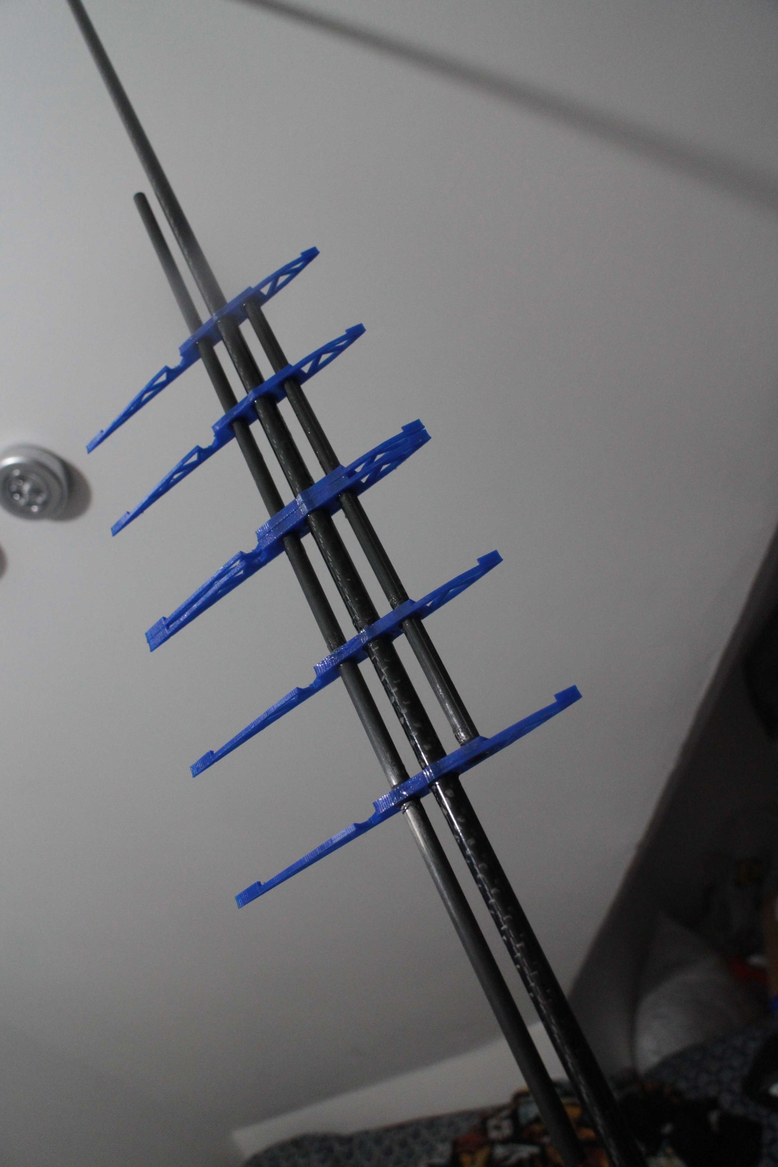
The first wing ribs glued onto the wing spars, the centre spar is the 8-6mm roll wrapped carbon tube, and the two outside spars are 6-5mm pultruded carbon tubes.

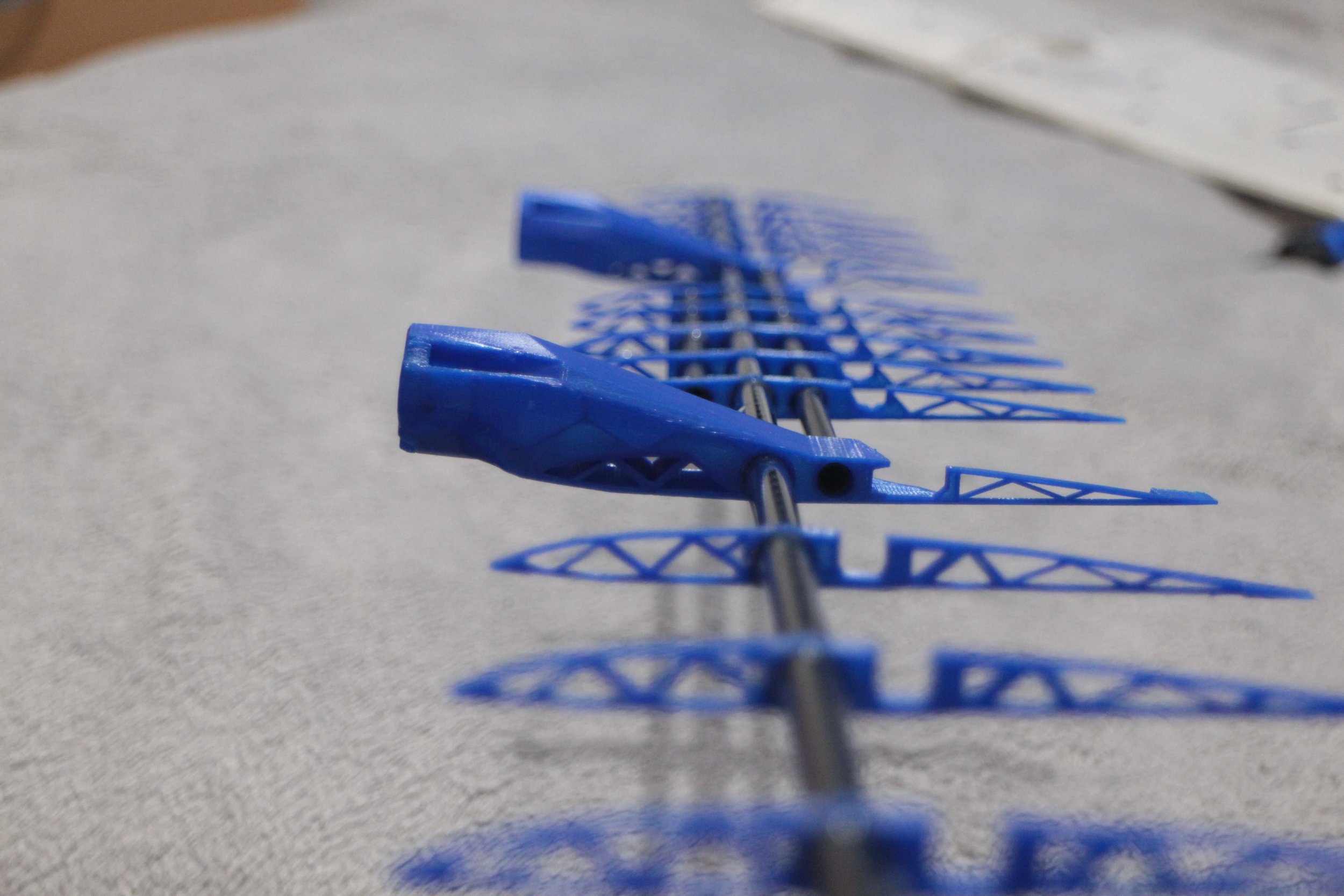

I cut this slot in the bottom of the hole for the spar in the motor mount to allow the hole to expand to fit. This turned out to be a problem later because as the hole expanded around the spar the motor angled upwards. to sort this, I had to make shims for the motor mount.

All the spars and ribs glued together including the outer wooden sections.
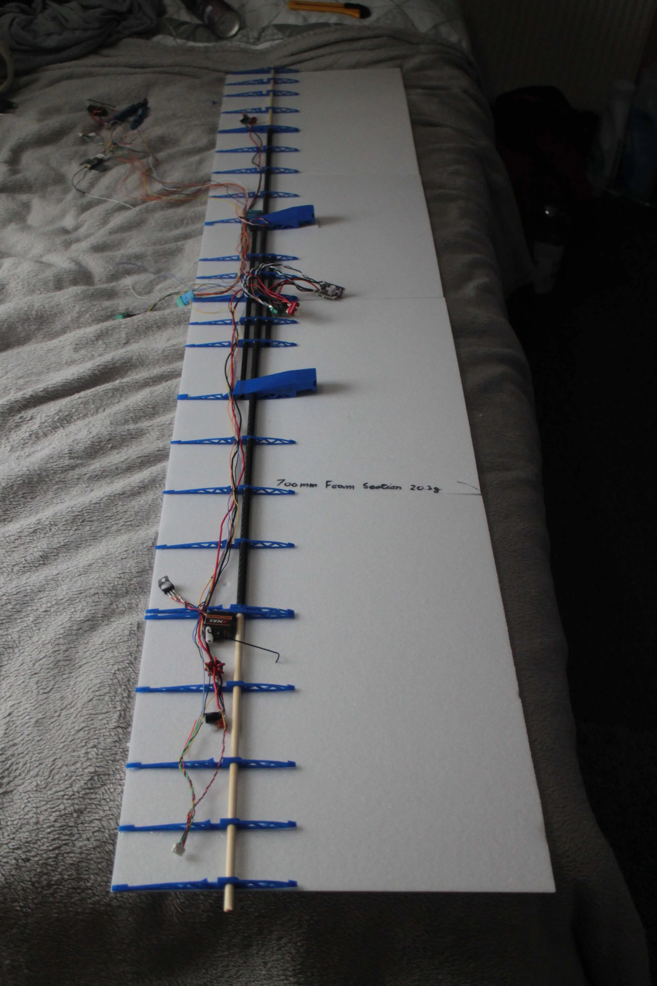
Laying out the electronincs on top of the wing to see how well they would fit.
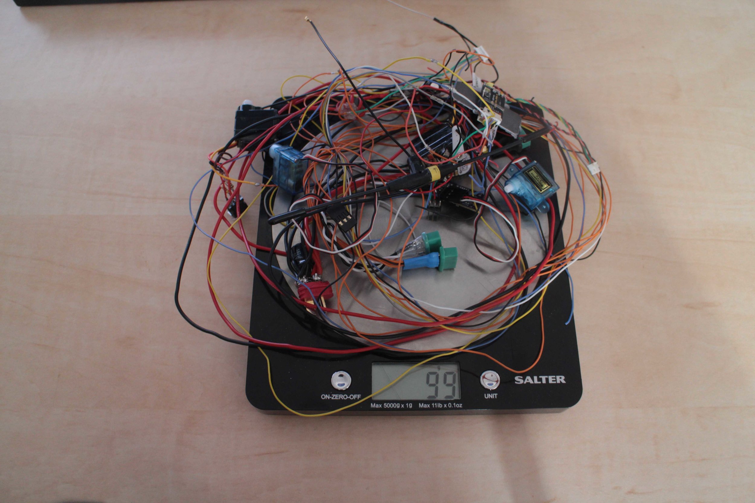
The weight of all the elctronics on the wing, excluding the motors and video transmitter.

Remounting the ESC’s in the same position as in the old wing.

One of the more minor changes I made was to switch to coaxial cable (from just a normal 30awg wire) for the analogue video transition line between the On Screen Display and the video transmitter. I’m using 50 ohm coaxial cable whereas it should be 75 ohm, but I correctly (it appears) assumed that it doesn’t matter too much in this case.
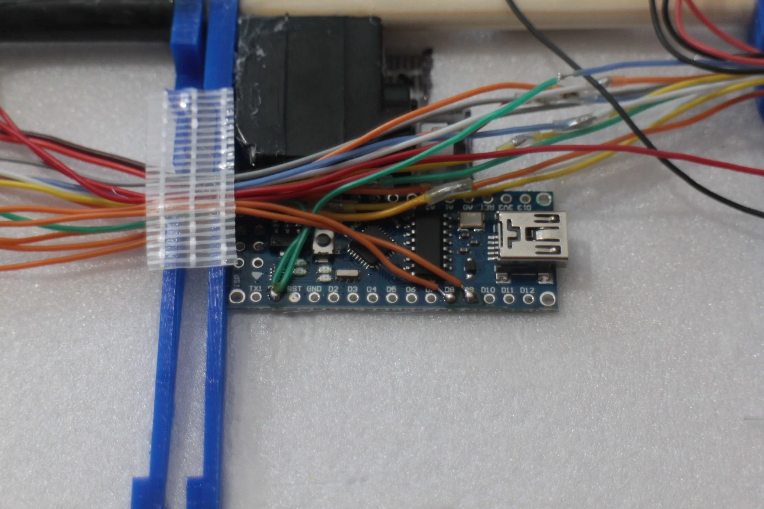
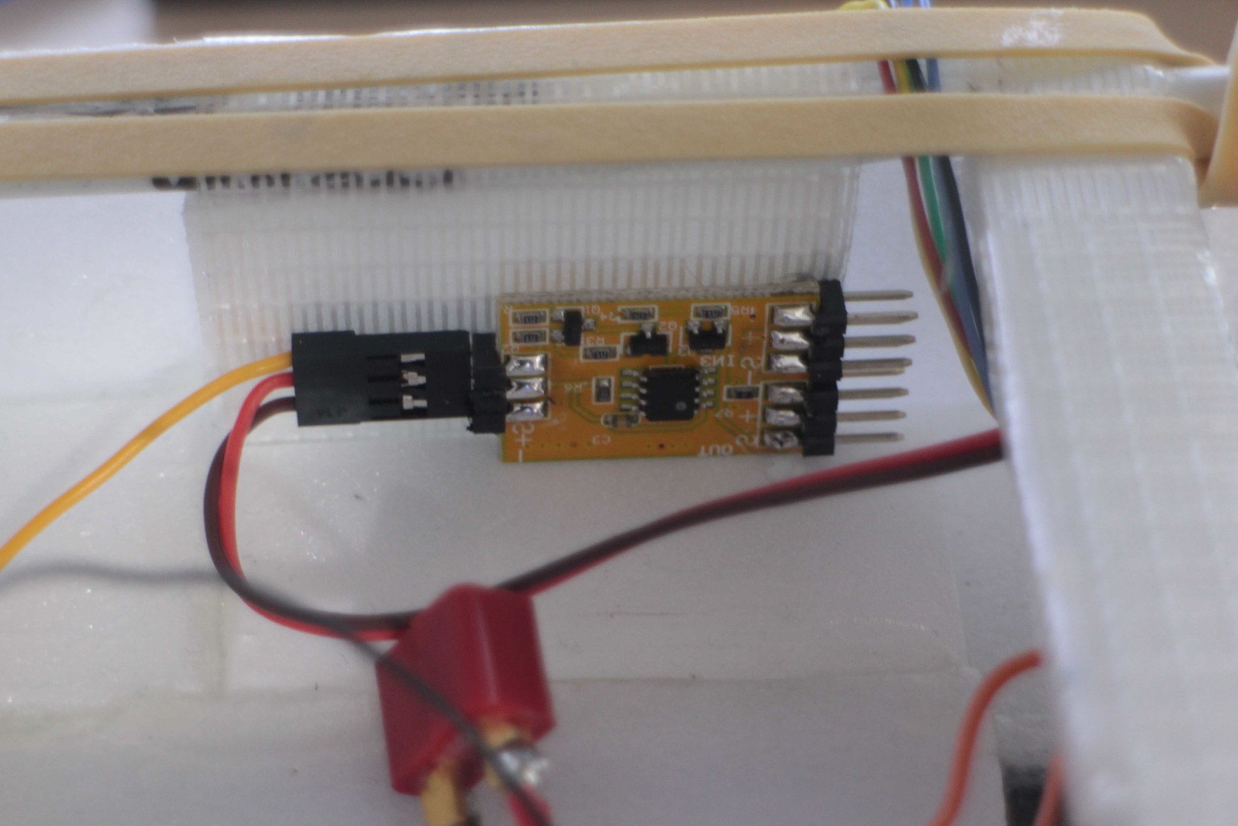
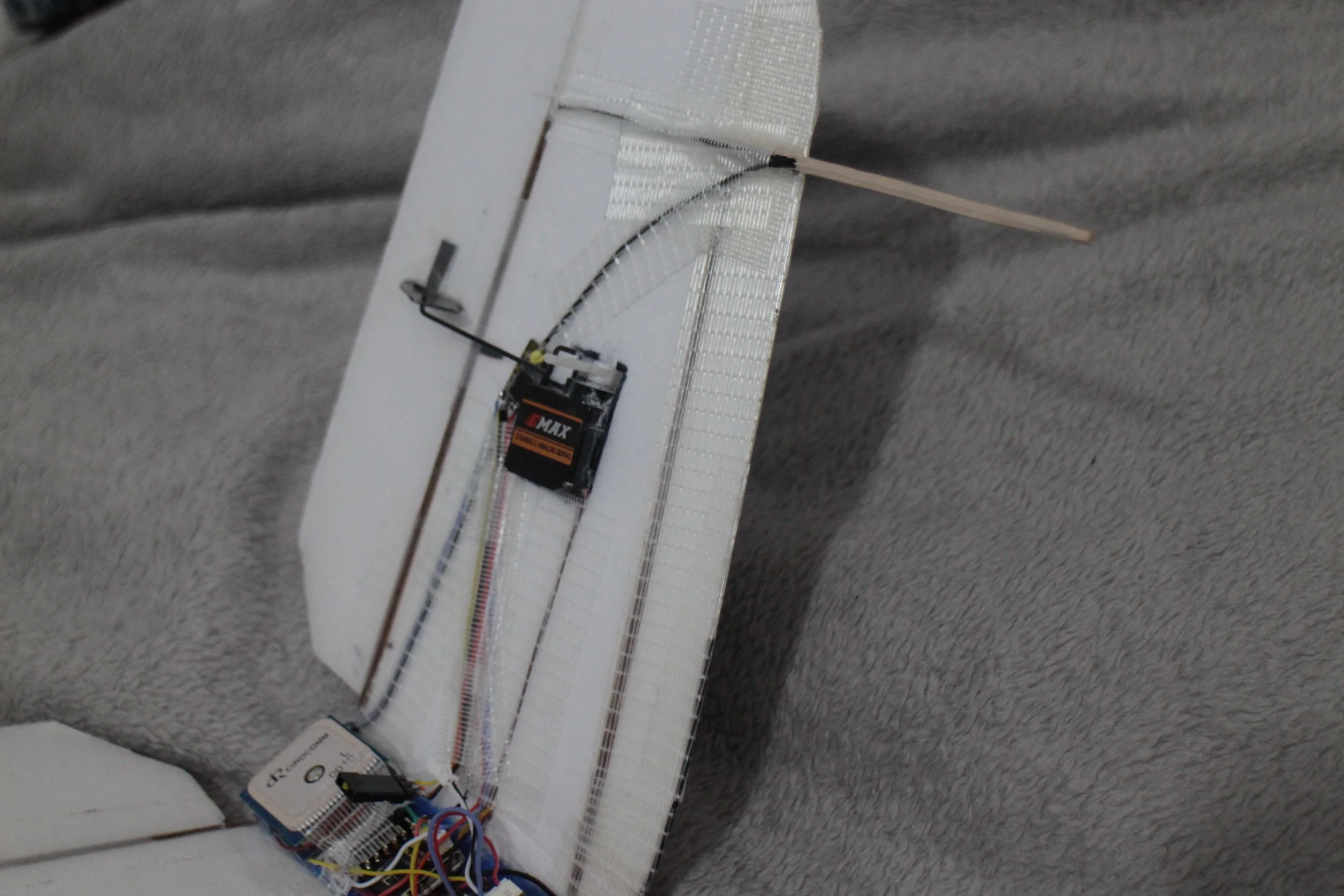
Arduino installed right next to the right aileron servo, near the main receiver. This is used to convert the Sbus signal from the receiver into The PWM signal needed to control the flap servos.
My code is just using a very simple implementation of the Arduino Futaba Sbus Library.

LM7805 Voltage Regulator to step down the battery voltage to the 5V that the flap servos need. Since these servos are smaller and use less current I don’t have to worry about cooling the voltage regulator.

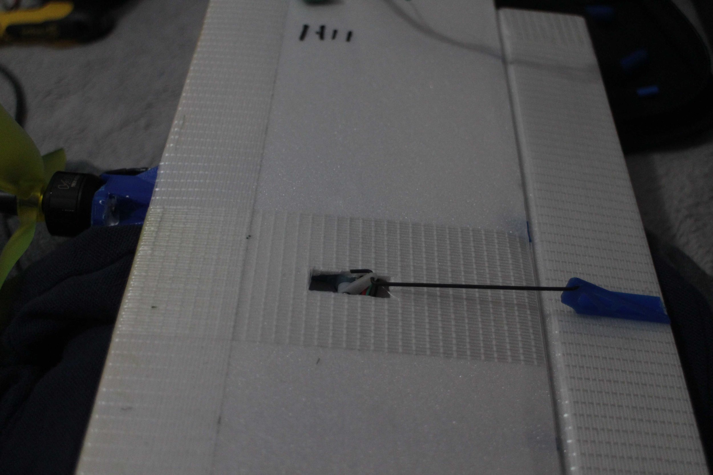
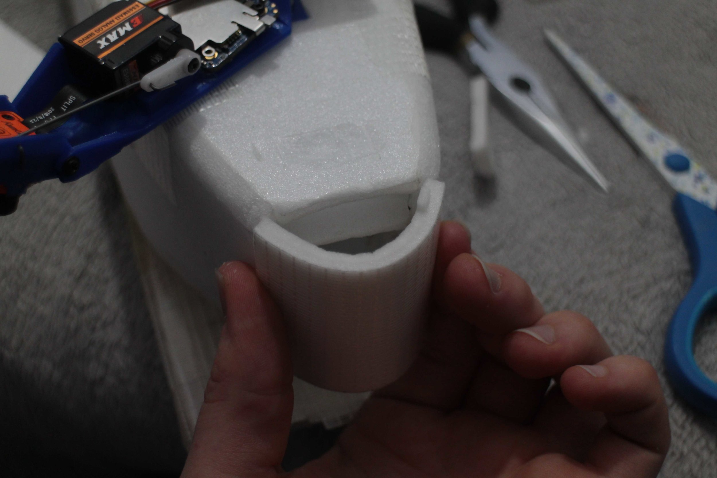
Cutout in the foam upper wing skin for the motor mount.

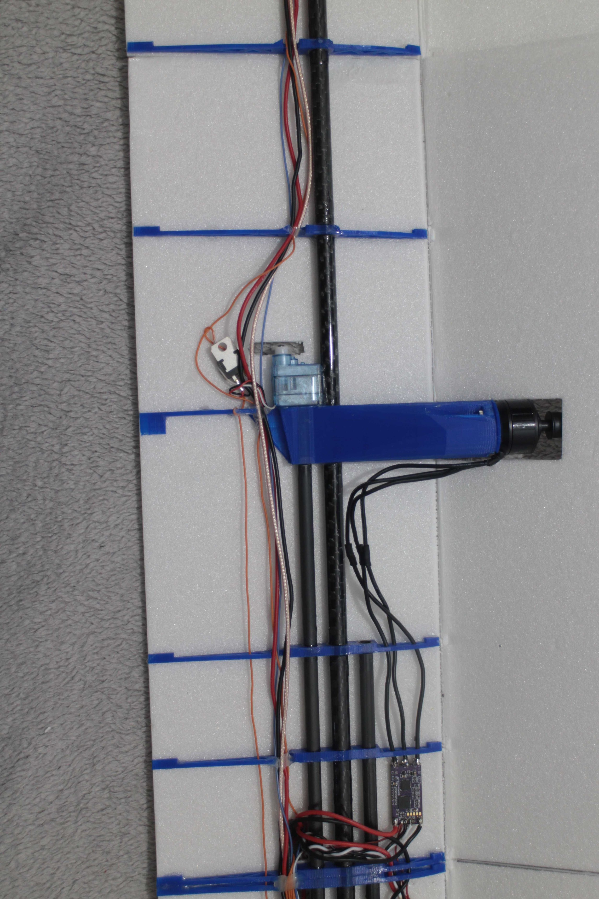
All of the electonics (except motors) installed in the wing.
Motors installed and foam creased, ready to fold over.

I have carried over putting the expanding foam in the leading edge of the wing from the V1.0 wing. It worked really well and made the leading edge of the V1.0 wing very durable.

Gluing a coffee stirrer into the trailing edge of the wing by the wing mount to prevent the rubber bands from digging into the wing, as was starting to happen on the V1.0 wing.

New wing next to the old wing.

I thought I would try using SolarTex Covering Film to cover the wing this time. It’s a type of shrink wrap that has long, natural fibres to increase its strength, it’s better for my use because it weighs less than half that of the glass fibre tape, and from my testing gives the foam the same if not more additional strength.

Unfortuanely all of my test pieces have been on flat sheets of foam without holes in, it proved to be much harder covering an already build wing.

Not coming out very well, I couldn’t heat up the covering enough to shrink it before the foam started melting underneath.

The top side didn’t go much better either, I decided to peal it all off and just leave it mostly uncovered as originally planned. Luckily this little experiment didn’t do much damage to the wing.
Flap servo linkage setup with the my 3d printed control horns.

The new wing came out 40g lighter than the old wing.

The new wing all done and on the fuselage, ready for the maiden!
Unfortunately…
Unfortunately, my ailerons were reversed for the first flight, apparently, I forgot to check control surface directions. Luckily, I managed to land it without any damage, so it was up in the air again a few minutes later.
As expected, the plane flew absolutely great, all the flying characteristics were the same as before and the flaps really slowed the plane down nicely. I immediately continued with developing the plane.
The first thing on the list was the pan and tilt camera mount, so I started designing.

The 3d printed 2:1 gear ratio for the camera pan and tilt mount that should have allowed for a 360* horizontal view, unfortunately it turns out that the servo only had 160 degrees of rotation. This will have to be redesigned at some point.

Skateboard bearings in use for the output shaft of the Pan gearing, to keep everything sily smooth and durable.

The top half of the camera pan and tilt system. On the left is the camera lens/sensor, in the middle is the tilt servo, and on the right is the Camera recording/control board.

70.5 grams for a (nearly) 360 degree by 90 degree pan and tilt system with a full 1080p HD camera, that also doubles up as an FPV camera isn’t bad in my opinion.

Gluing the bottom half into the fuselage.

Bottom half glued into the fueslage, with one of the prototype parts on the right of the frame.

Mounts onto the fuselage with a very low profile.

Overall extremely happy with how this turned out, it’s the lowest drag design of any pan and tilt system I have seen, and it still maintains a low weight and high simplicity. It looks relatively odd having the point of rotation of the ‘pan plate’ being so far back, but this is so that the camera can look straight down in any direction (other than backwards) which yet again, I haven’t seen from any (top mounted) other design. This also makes the system appear to have lot of backlash since the camera has 5-10mm of backlash, but realistically, only the angle matters and that it roughly constant regardless. I had thought about putting a ‘strake’ on the back to aerodynamically stabilise the pan plate, but in testing there was no problems whatsoever from the get go.
My first propper attempt at chasing a line of sight plane with FPV, lots of fun, unfortunately not great video quality from the runcam split mini 2, needs some investigation.
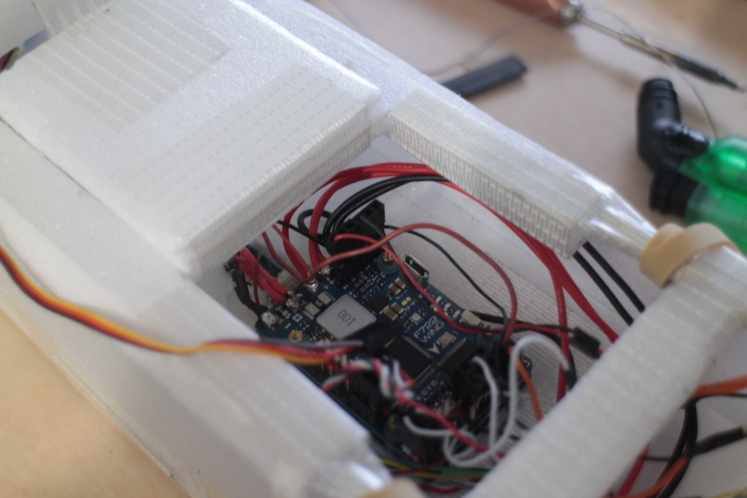
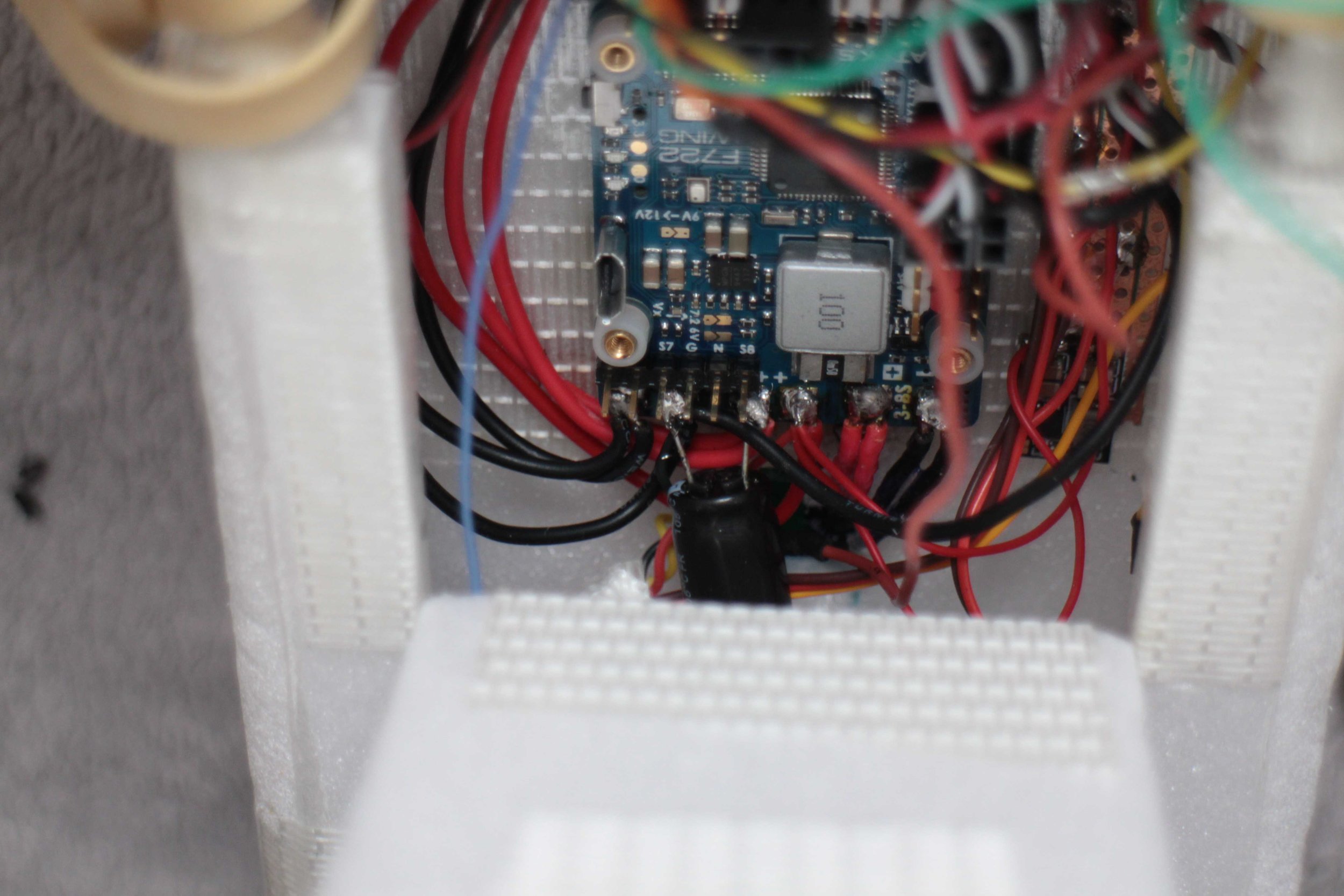
With some of the new parts I was adding I decided to rewire the flight controller.

I also decided to add a simple power distribution / 5V stepdown board, which just consists of some perf board, a switching 5V regulator and a linear 5V regulator.
Added a video switcher, ready for adding the second camera and second OSD.
Finally made a fairing for the nose of the plane, as it turned out the plane was completely fine with no airflow in the fuselage, so I covered it up to lower drag and buffeting.

The pan plate is just long enough to clear the nose

Much more aerodynamic now.

Second 900MHz receiver being added. The first one has two antennas, so between them both I have all three 90degree polarisations.

(Centre of frame) Redundant 2.4GHz receiver being added.

Redundant second camera added.
All the wiring on the tail finished and taped over.

Unfortunately adding the second camera seems the have added these rolling horizontal and vertical lines. I’m guessing that this is due to sync pulse interference, but I’m way out of my depth with analogue video to know whats going on.
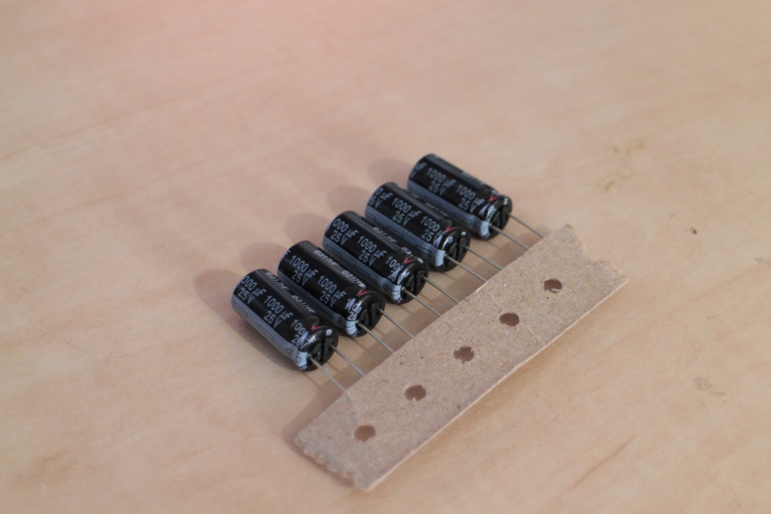
I bought some Low ESR Panasonic FR Series 1000uf Capacitors, I thought they may help with the issue and was wanting a reason to justify getting some nice, expensive low ESR capacitors anyway.
I added one close to camera on the tail across its power supply lines and it seemed to help a bit, making the lines a little less darker. I didn’t get to find the cause of this problem because it went away the next day without changing anything (as far as I’m aware) and didn’t come back.
A few days later I also replaced a standard 500uf capacitor with one on the output of the ammeter built into the flight controller. This helped to stabilise the ammeter readings significantly.

Finally making wingtips for the plane, almost 4 months in the making!

Foreground: after 4 months of hard flying the tail boom came loose and cracked the flimsy foam fairing. I cut it all away and reinforced the tail boom mounting point with 3mm plywood making it rock solid.
Background: the blurry wingtip can be seen on its debut, surprisingly it made no difference in flight characteristics, this is the first time I had tried this type of 45* up 45* down wingtip and I think I have misunderstood how/why it works aerodynamically on the latest passenger jets. I will have to investigate further in the future.

Installing the second On Screen Display, this is a whole second flight controller with a second GPS, but I’m only using it for the OSD. In the case that my main flight controller fails or main GPS stops working this one should still be fine meaning I will still be able to navigate using GPS. Note this GPS is mounted at 90degrees to the other one, meaning this GPS should keep signal if the plane was upside down for a long period of time.

Foam fairing for the servo, on this side of the V-tail it also doubles up to cover the secondary 900MHz receiver.
This was flown completely line of sight, which is why the video is quite bumpy and erratic.
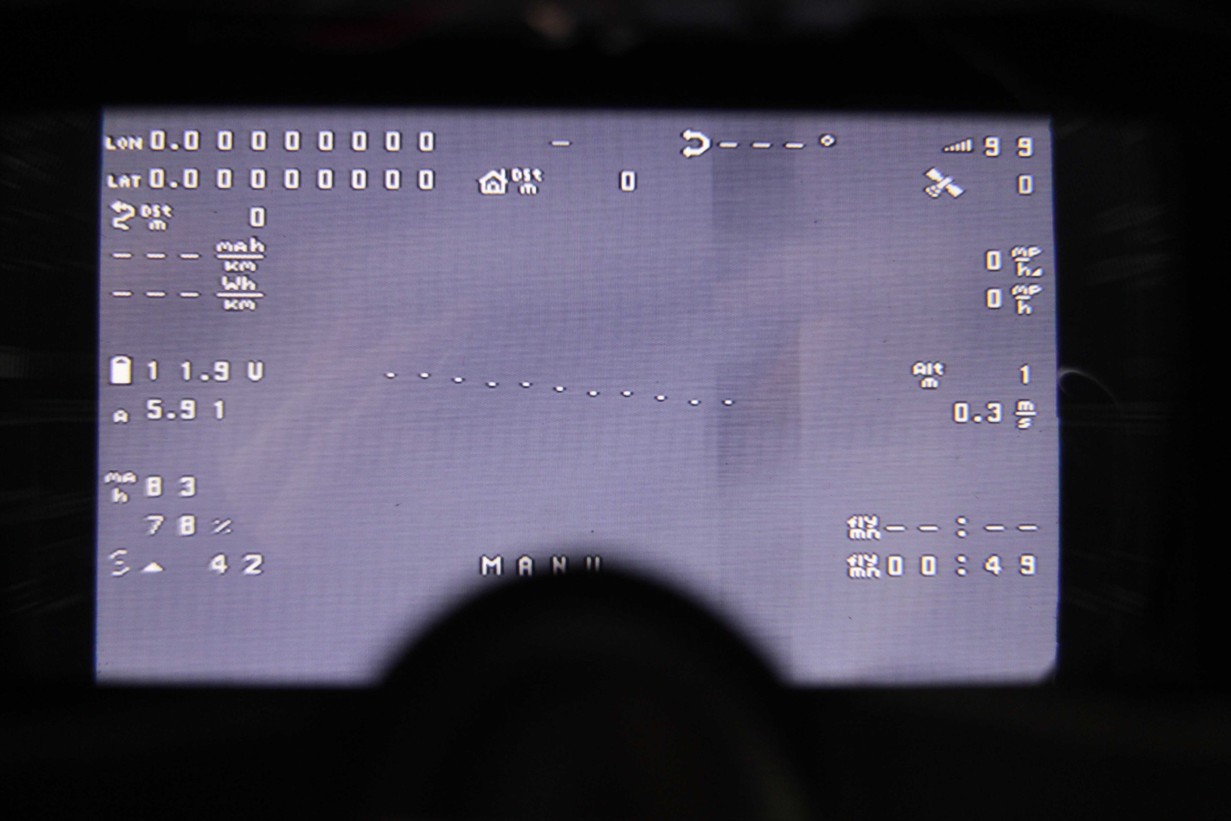
The plane flew for a total of 47.2km in 1 hour and 3 minutes. Over this time the plane drew 10000mAh from my Hybrid Battery Pack setup with 2x 3s 2200mAh Lithium Polymer batteries and 2x NCR 18650B 3s 3400mAh Lithium Ion Battery packs. These have a total theoretical capacity of 11200mAh, and a minimum voltage of 8.5v, meaning there was still some energy left in the batteries as a reserve.
This gives an average current draw of 9.7 amps and an average efficiency of 212mAh/km.
Once I switch to my hybrid battery pack with 4x NCR 18650B 3s 3400mAh Lithium Ion Battery packs which would have a total capacity of 18000mAh and only weigh 300g more, I should immediately be up to 75km of range.
With other improvements such as reducing the current requirement to 7-8 amps with different propellers which I believe should be possible and considering the 10 gusting 15mph winds in this video, I should be able to increase the range to the neighbourhood 120km.
Overall, the plane performed less well than I wanted, but there is a clear path to improve this.

Weighing the finished fueslage.

The fuselage weighs 417g without the camera pod.

Camera pod weighs 80g.

Wing weighs 529g.

Wing being weighed, and another view of the wingtips.
The Crash

I was flying late in the evening, just after sunset, doing aerobatics and general flight testing of the plane which I had been doing for the last week.
The wind was 20 gusting 30 mph and the visibility was low with it being so dark, but it was the only time I was able to fly, with the preparations for D-Day commemorations in Portsmouth meaning that I wasn’t allowed to fly during the day.
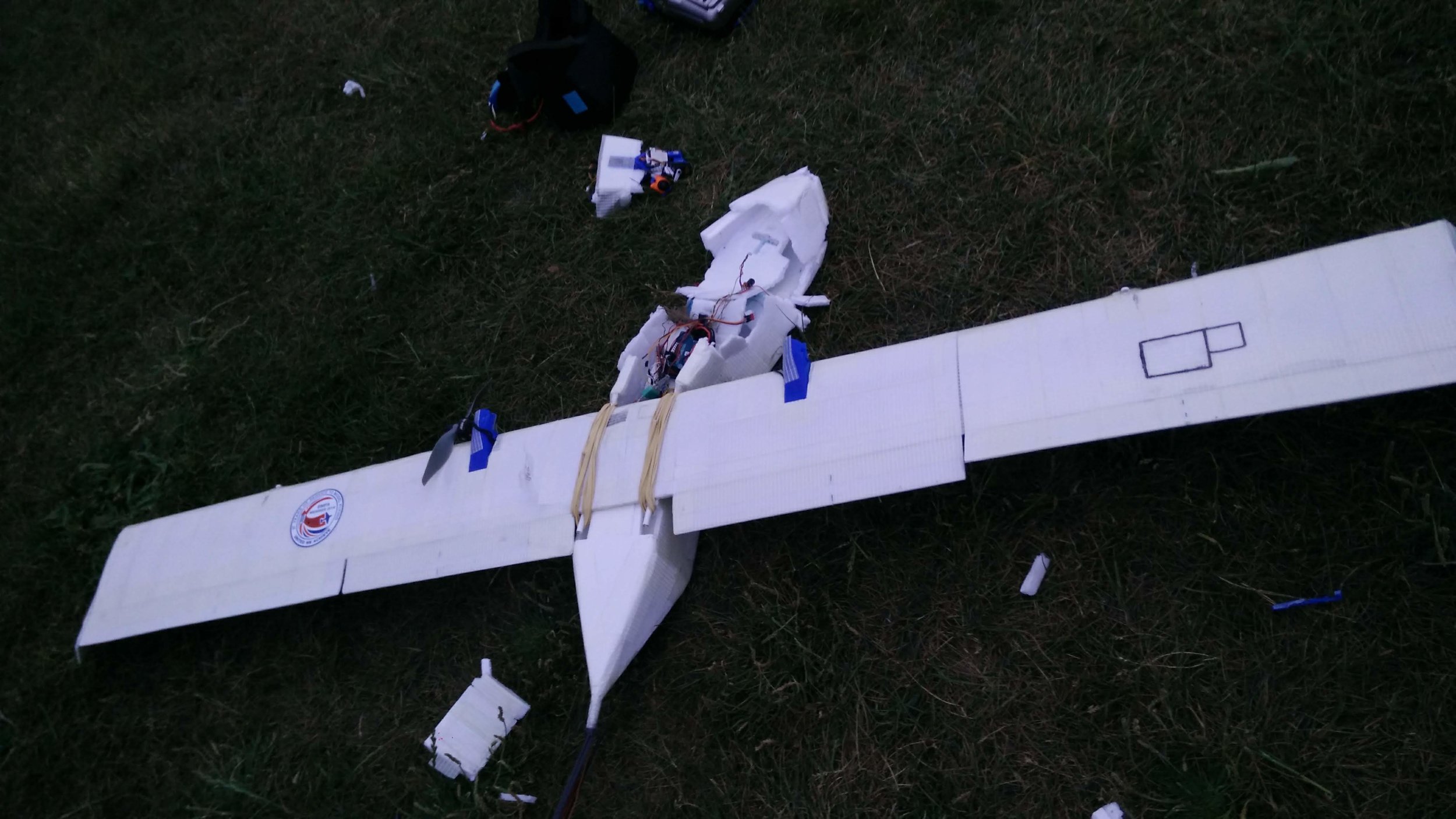
I was coming into land on a low downwind (I had already lost more height than I wanted on the crosswind to downwind turn), and a large gust of wind rolled the plane violently to the right. I managed to level the wings, but I had lost too much height and the plane hit the ground hard. The plane would have been salvageable if it wasn’t for the strong winds which meant that the plane was potentially flying at >80kph when it hit the ground.
This crash was very demotivating as with the new motors, propeller and improved wing tip design (I cut off the top 45 degree plate) I had got the plane down to drawing 5 amps while at a 50kph cruise. This meant that with the hybrid battery pack that I had now finished and proven to provide 16000mAh, the plane would have had a range of 140km. And I figured there was still room to improve.

The new motors and propellers that I was testing, these were exactly the type of motor I was looking for 6 months ago when I built the first plane. Now, because of the ‘6s battery’ craze with racing quads, this type of motor is being made. I will explain further why these are better in the V2.5 build.
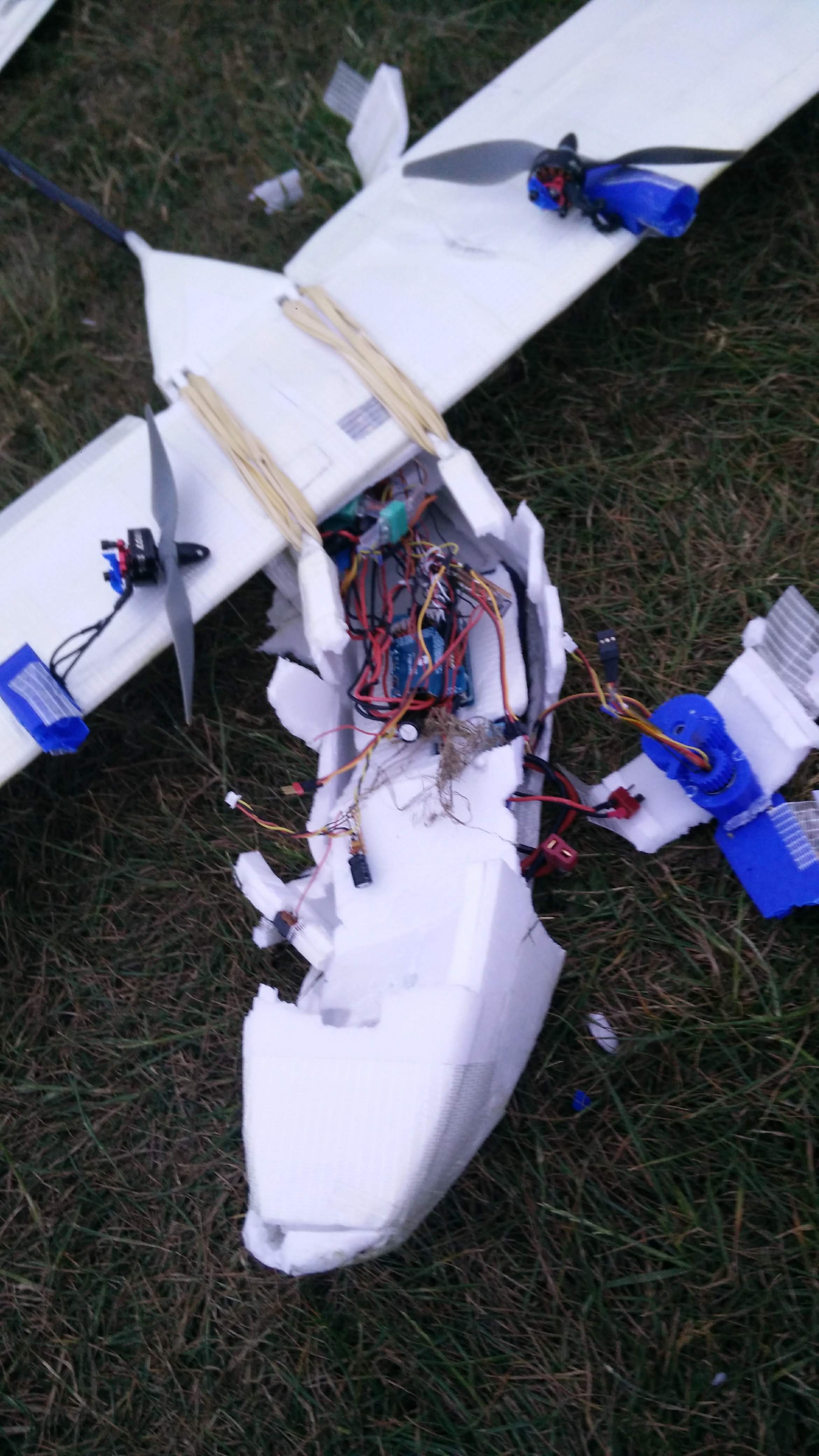
Front of the fuselage is absolutely destroyed.


Even the wing skins delaminated from the ribs it was such a violent crash.
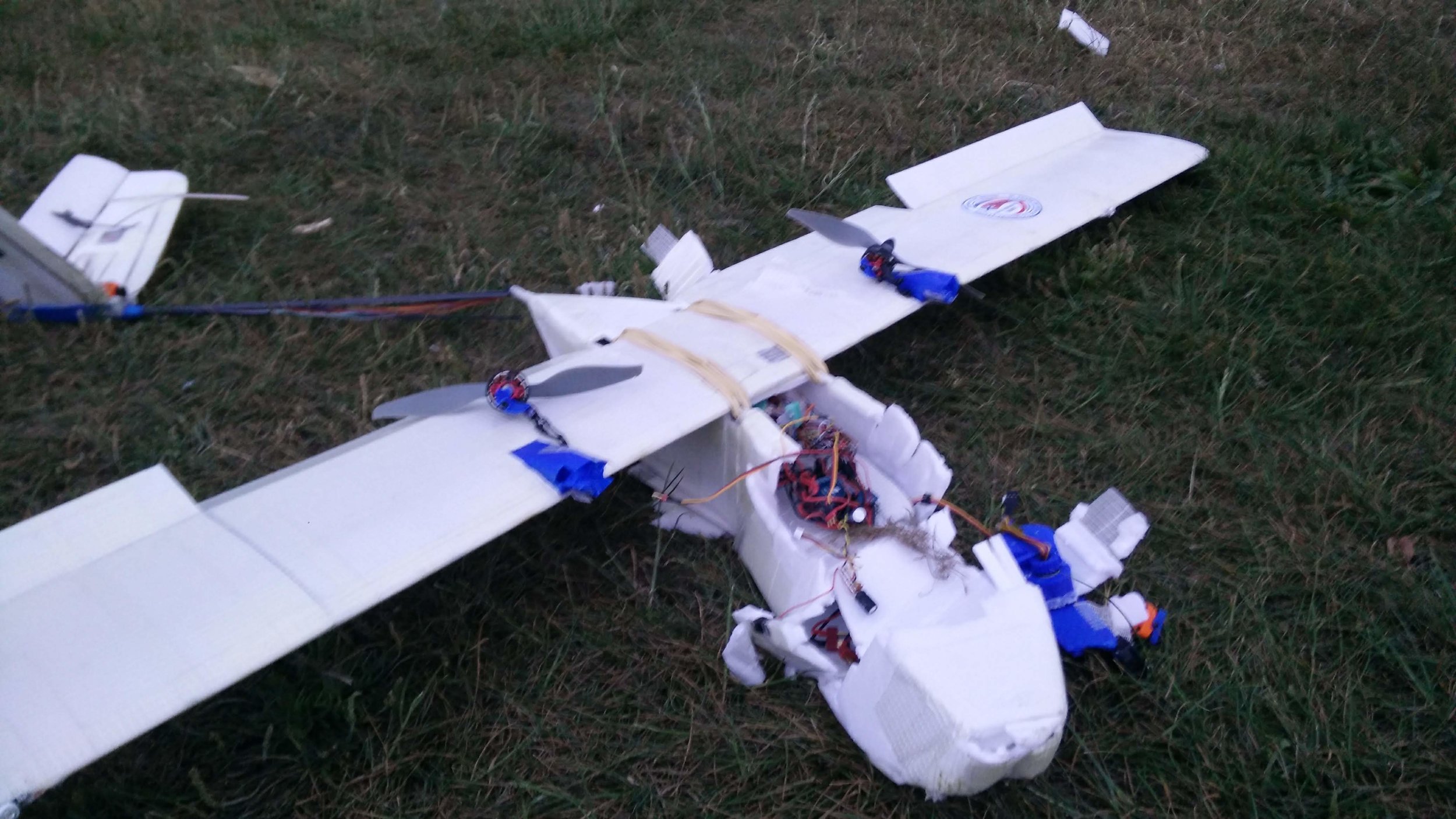
Luckily, as the plane was designed to do, it protected all of the electronics meaning that I was able to reuse everything for the V2.5 build.
This plane was going so well and had nearly got it to where I wanted it, and had already exceeded expectations in many ways.