
June 2019
Long Range FPV Plane V2.0

Mission With Version 2.0
Overall, I was very happy with V1.5 before the crash, so the main aim is going to be some minor improvements, mostly to reduce the weight of the plane and increase its strength.
The biggest change I want to make will be reducing the wingspan by 100mm (and reducing the chord length and wing thickness to keep the same aspect ratio and Airfoil respectively), this should allow me to both increase the cruise speed (due to decreased parasitic drag) and it should increase strength (due to decreased moment arm of the wing).
I then hope to keep the stall speed the same despite the decreased wing area by reducing the weight, as already stated, but also by increasing the length of the flaps and decreasing the length of the ailerons. This will allow the flaps to be more effective at the cost of reduced aileron control. However, the aileron control was already more than enough, and towards the end of the V1.5 I had been successfully testing using the flaps as ailerons. This will then give me more aileron control at the flip of a switch, if needed. The aileron control will also naturally be a bit better due to the decreased wingspan.
I will further be decreasing the weight of the plane by switching to SolarTex to cover the wing instead of Glass Fibre Tape. Last time this didn’t go very well because I tried to apply the SolarTex after forming the wing skin around the wing ribs (and because of my lack of skill), This time I will be applying the SolarTex to the flat sheet of foam first. This should allow the application of the SolarTex to be much easier. I also bought and have been experimenting with a new temperature-controlled heating iron that makes the process easier.
Now I know that I don’t need cooling airflow for the components in the fuselage, I will be building the front and rear fuselage fairings directly into the design of the fuselage, this will decrease weight and increase rigidity, especially around the tail-boom area, where the foam fairing will now be part of the fuselage and will become a structural part.
This will reduce the flexing of the tail-boom making the tail more effective, allowing me to both reduce the length of the tail-boom by 25% (reducing the moment of the tail by ~15%) and move the motors out further on the wings by 20mm per side since the tail will still be able to maintain yaw stability in a motor out situation. The shorter tail-boom will allow me to change the tail-boom from an 8-7mm pultruded carbon tube to a 12-10mm roll-wrapped carbon tube, without increasing weight, and the motors being mounted further out on the wings will allow me to fit larger, potentially more efficient, propellers.
Further, since I have now designed a pan and tilt system for the camera, I am going to reshape the nose of the plane so that the pan and tilt system can be moved forward. This then means I can reduce the overhang of the camera pan plate while still being able to look down over the front and the sides of the plane.
Ironically, this means I also need to redesign the camera pan and tilt system to make it shorter. This is a blessing in disguise though because it will allow me to reduce its weight a bit and while I’m redesigning it, I’ll increase the gear ratio from 2:1 to 3:1, giving me a true 360 degrees of horizontal rotation.
Along with these new improvements I will also be carrying over all the changes made to V1.5 over its lifespan.
And before I know it I’ve gone from some minor improvements to a complete redesign…

I started off with designing the parts for the new pan and tilt system, while waiting for parts to arrive for the rest of the plane.

Pan servo mounted in the pan tilt system.

New larger driven gear for the 3:1 ratio, becuase of this I removed the other half of the gear to save weight.
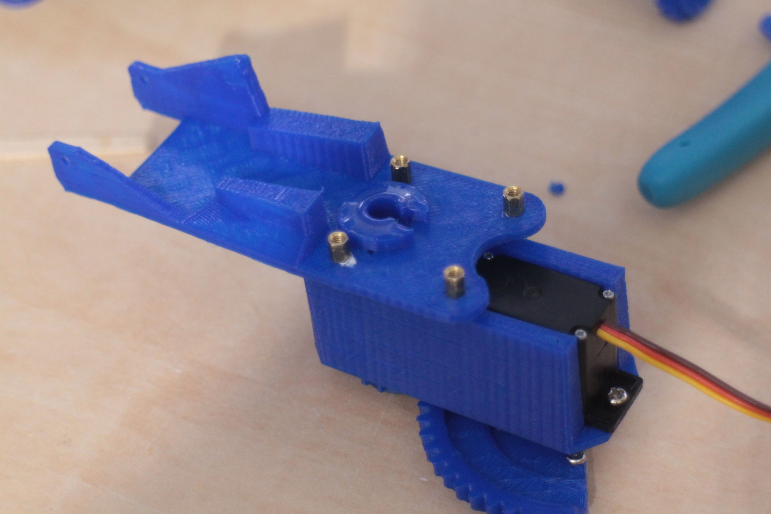
This shows where the new pivot point is on the pan tilt system, the pivot point is moved 30mm forward, putting it almost in the centre of the pan plate.

Top view.
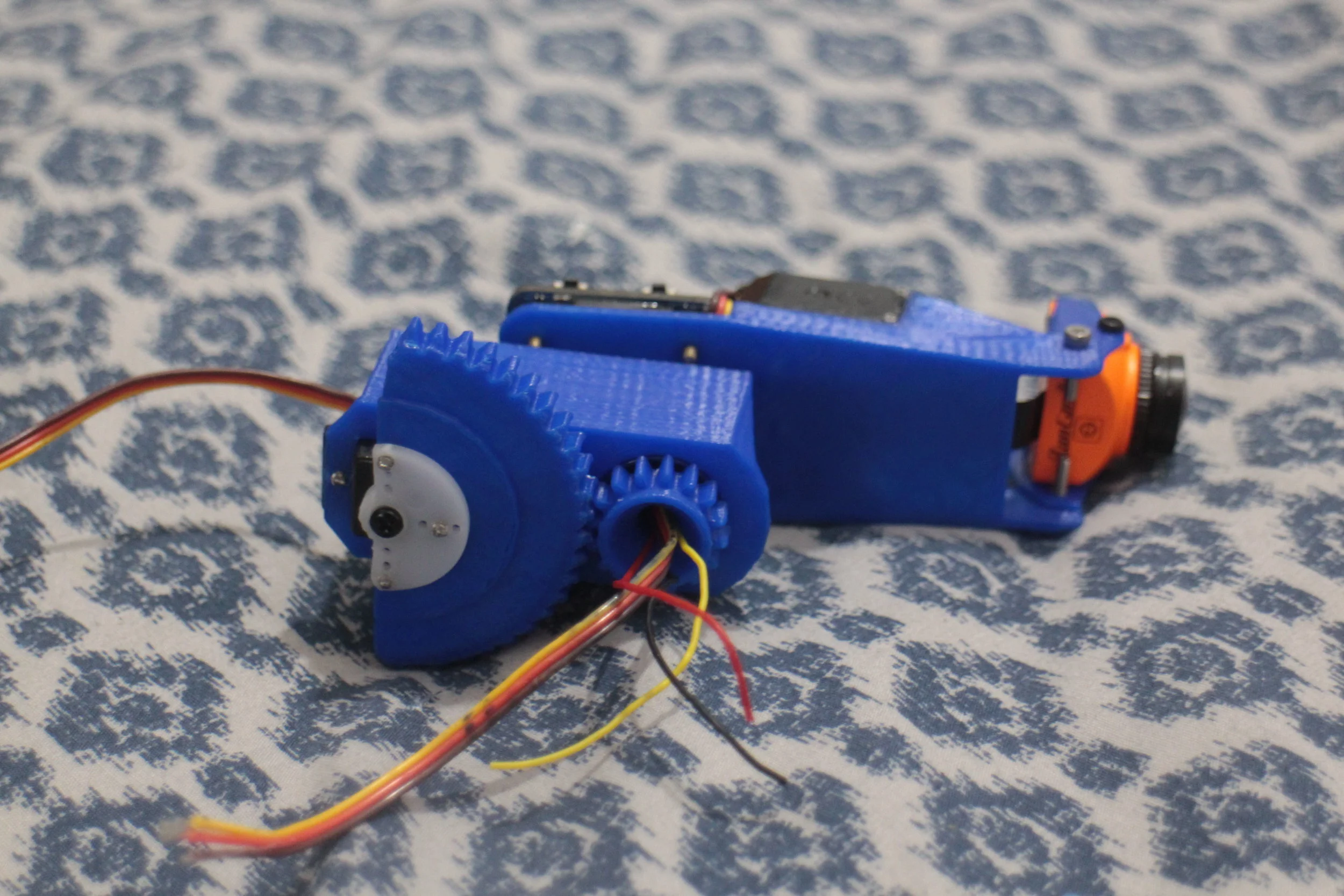
Bottom view.
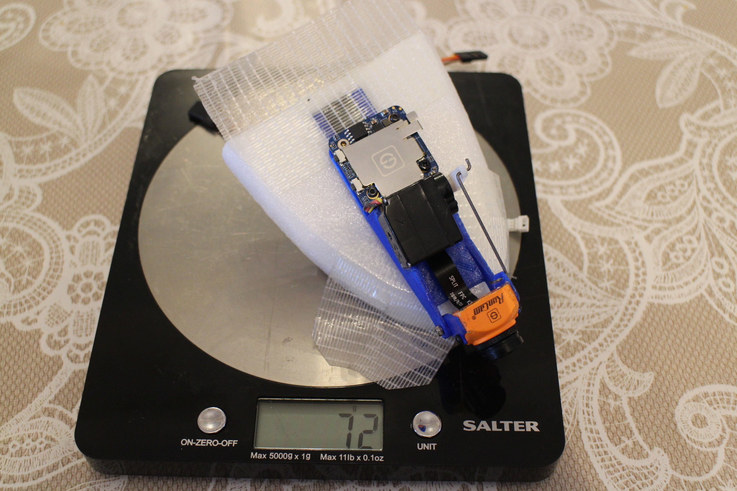
The new pan tilt system weighs 8g less than the old one, thats a 10% decrease in weight, with extra functionality!

All of the 3D printed and laser cut parts required for the plane.

Fuselage coming together. It is a much quicker process now that I’ve laser cut everything. And it even appears that I got all the dimensions right in the designs!

Tail dry fitted together with new 9mm foam and redesigned plywood reinforcement. Dry fitting did not come back to bite me this time, luckily.

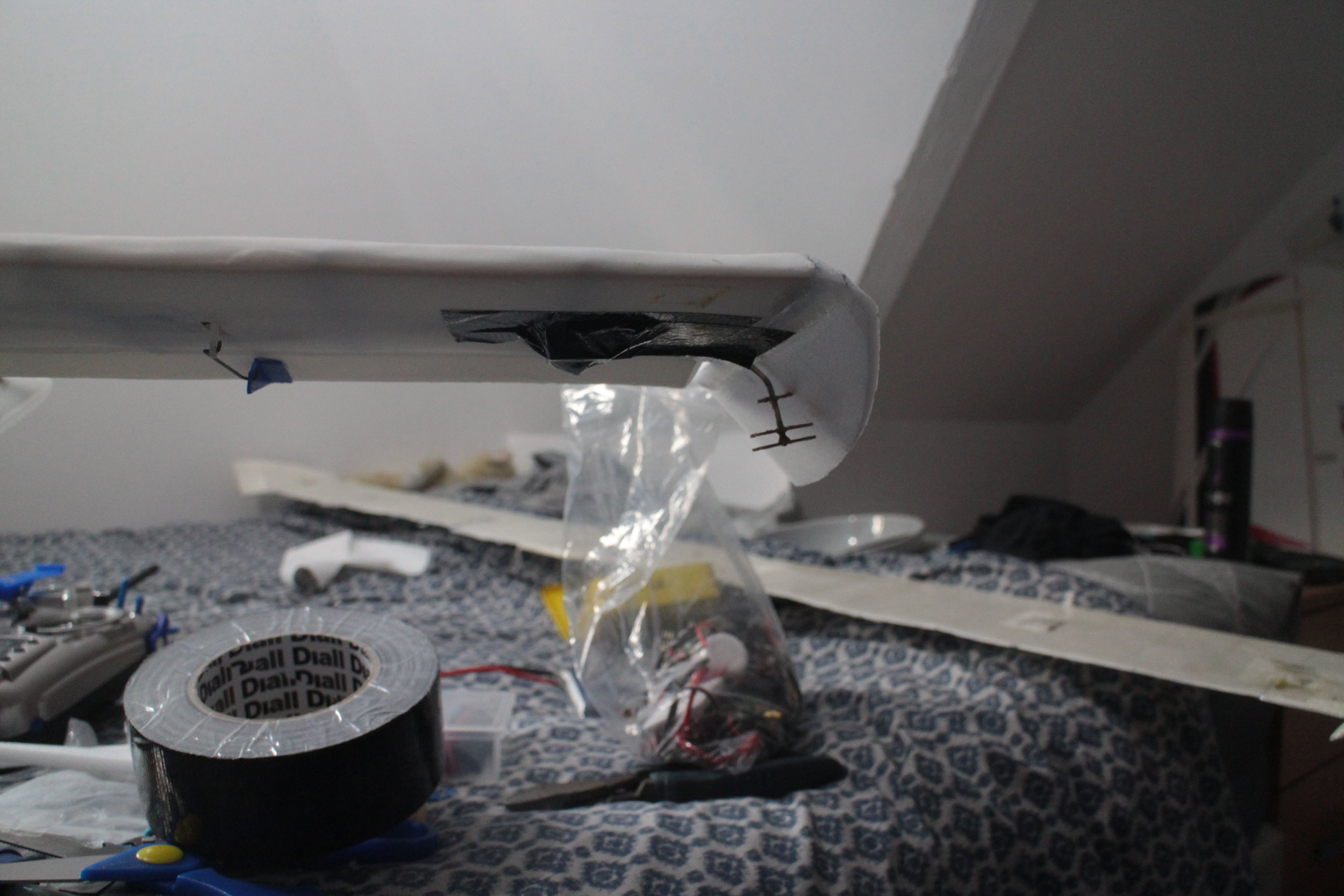
Boom mount, particularly showing how the fairing is now structural.

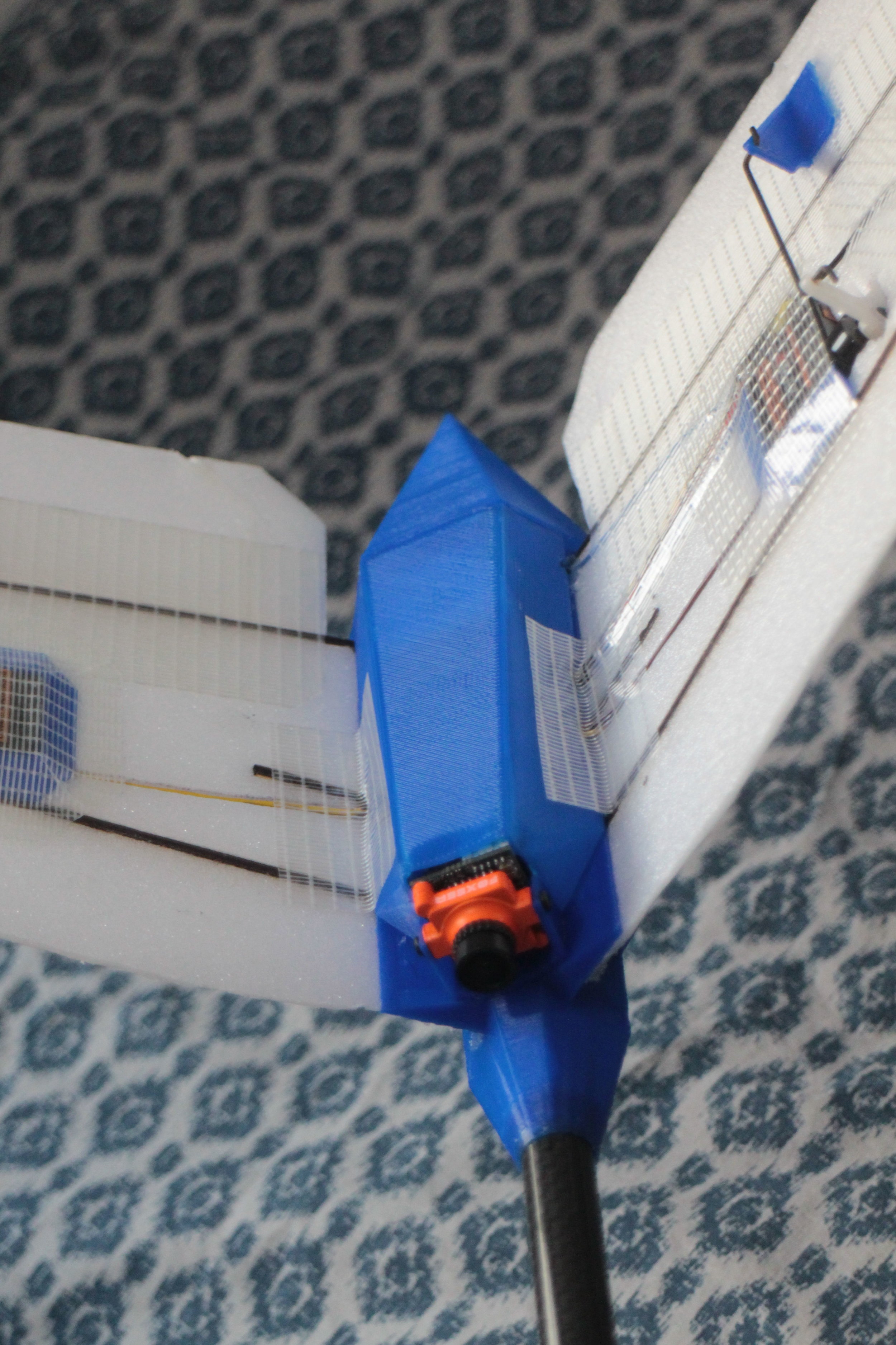
Pan and tilt system mounted on the fuselage. This time i have designed it so that it is more easily removable for maintenance.

Fuselage airframe mostly done.
New cover for the tail electronics, it provides no real advantage over using tape, and probably weighs more, but it definetely makes it looks a bit cooler.

Tail finished.

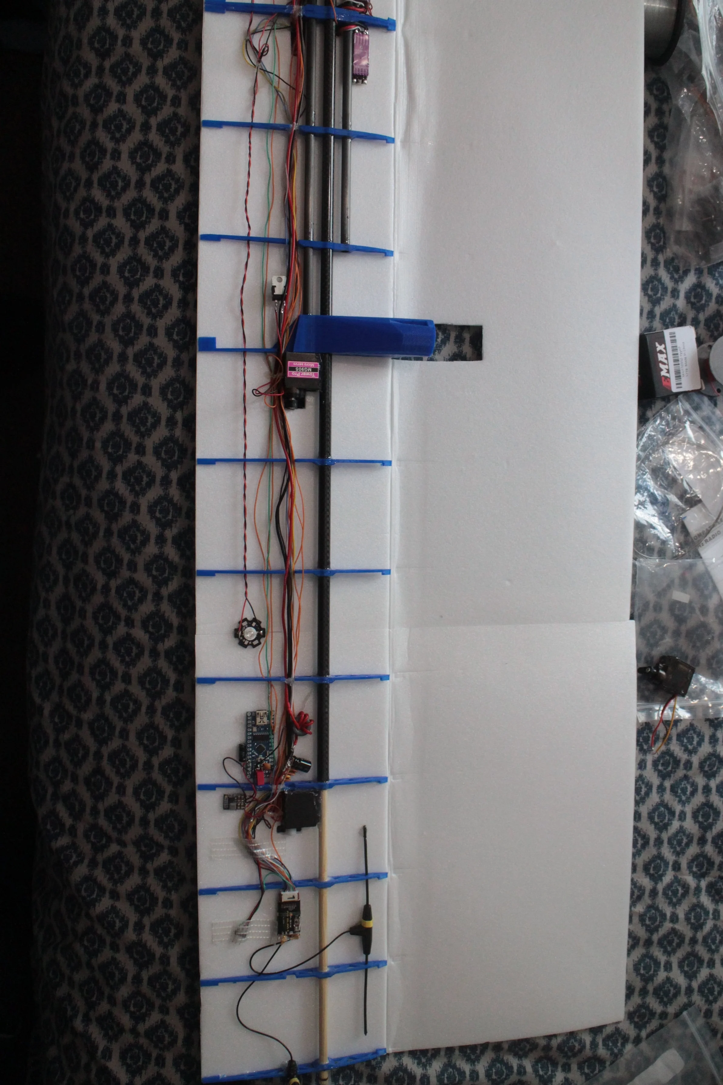
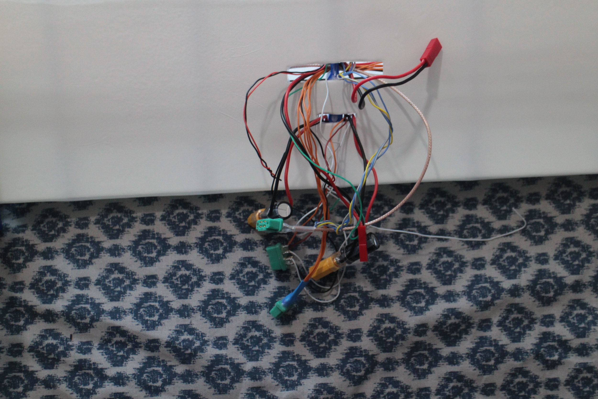
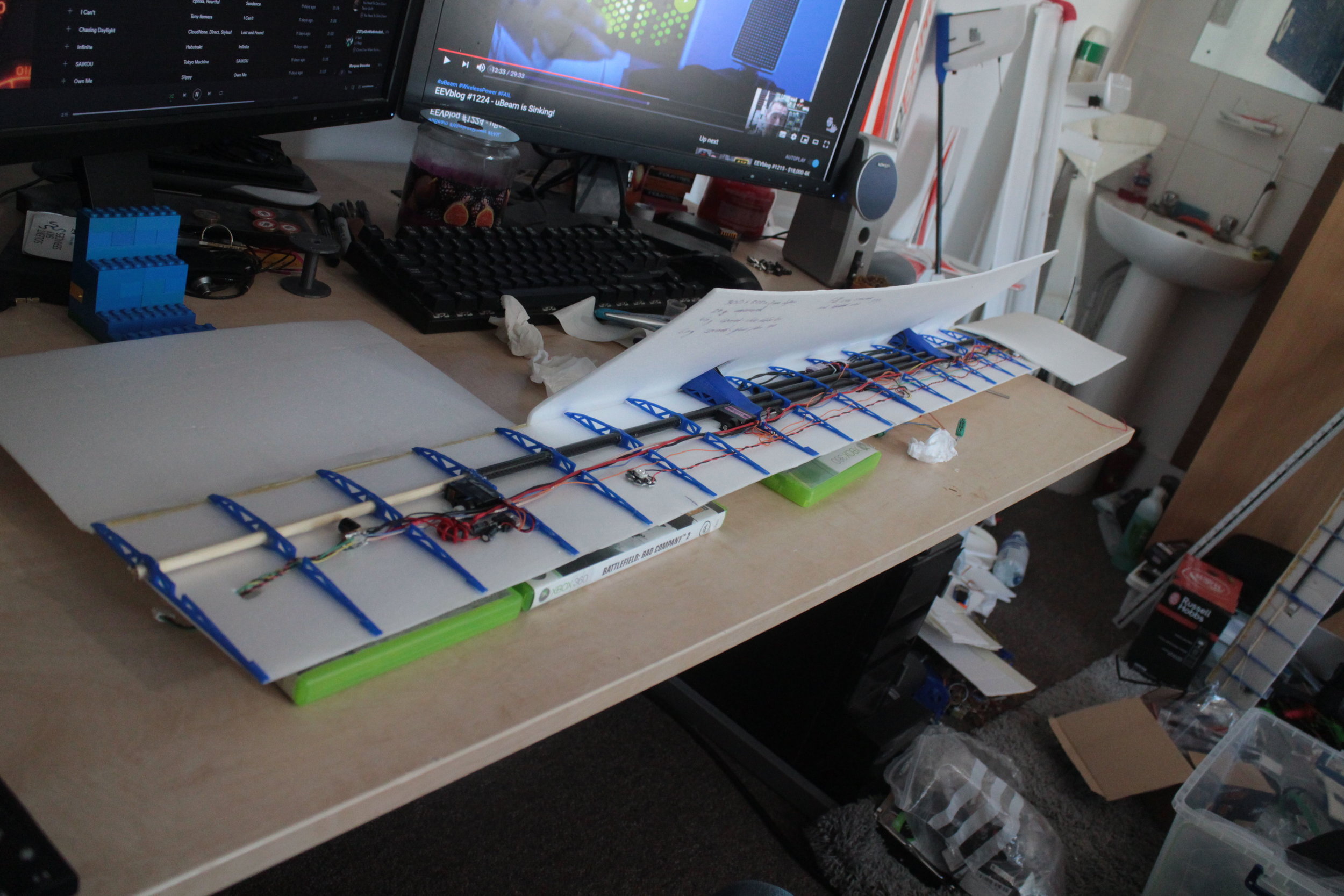
Begining to mount the electronics in the fuselage.
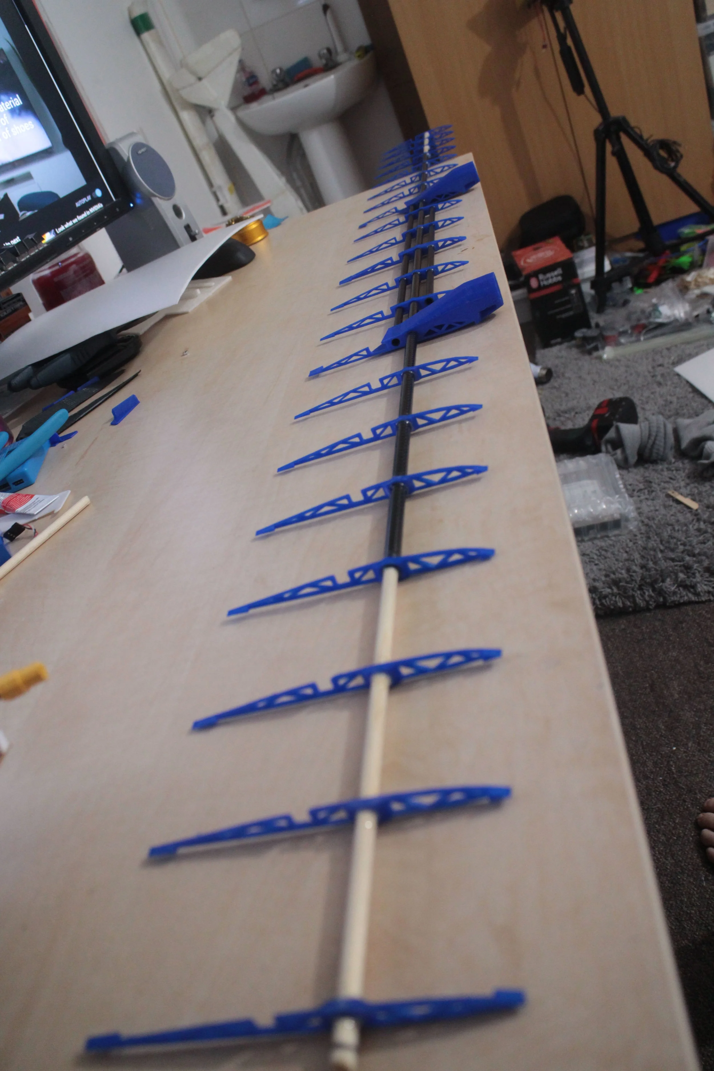
Internal structure of the wing glued together. It is all the same as V1.5, except each of the outer wooden sections are 50mm shorter.

The new V2.0 wing next to the old , torn apart V1.5 wing.

Left half of the wing internals.
Right half of the wing internals.

Another view of the inside of the wing.

I’ve saved 15g per wing side just by switching from glass fibre tape to SolarTex, and its stronger.
Wires exiting the wing.
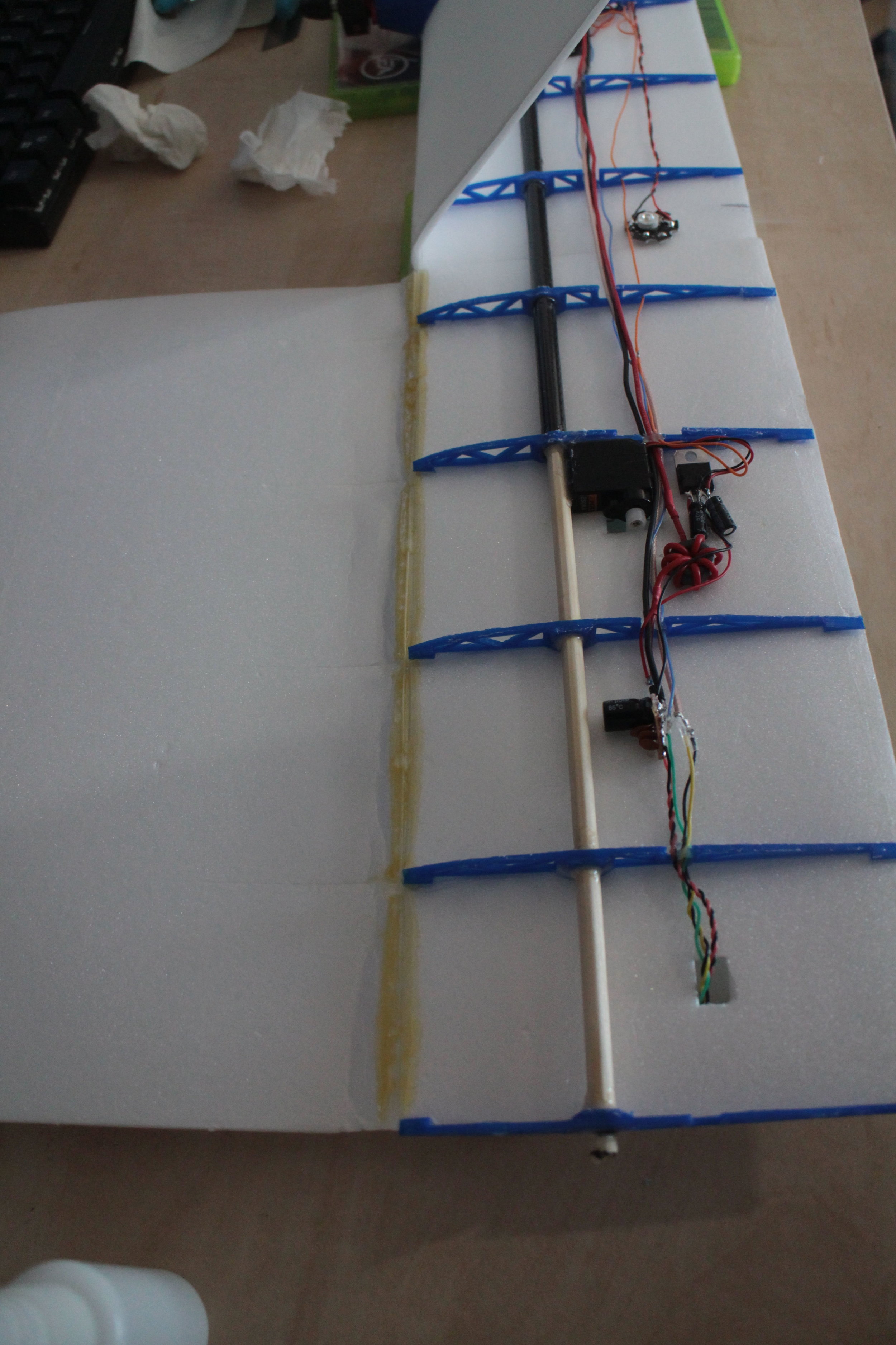
Using the expanding foam in the leading edge of the wing for durability, as in V1.5, however cutting back the amount to reduce weight.
Creasing the foam while getting ready to fold over the top wing skin.

A last look inside the centre section of the wing.

Laser cut wingtips glued onto the ends of the wings. These are the same design as the final V1.5 wingtips.
Video transmitter temporarily mounted with tape onto the underside of the wing, so that i can easily swap between video transmitters for comparison.

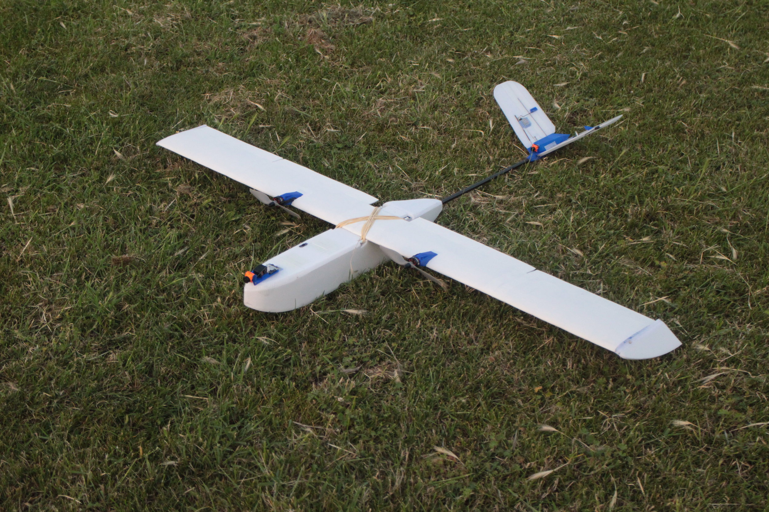
Plane finished and ready for the first flight.


8g weight saving over the V1.5 pan and tilt system, as mentioned earlier.

25g weight saving over the V1.5 fuselage.
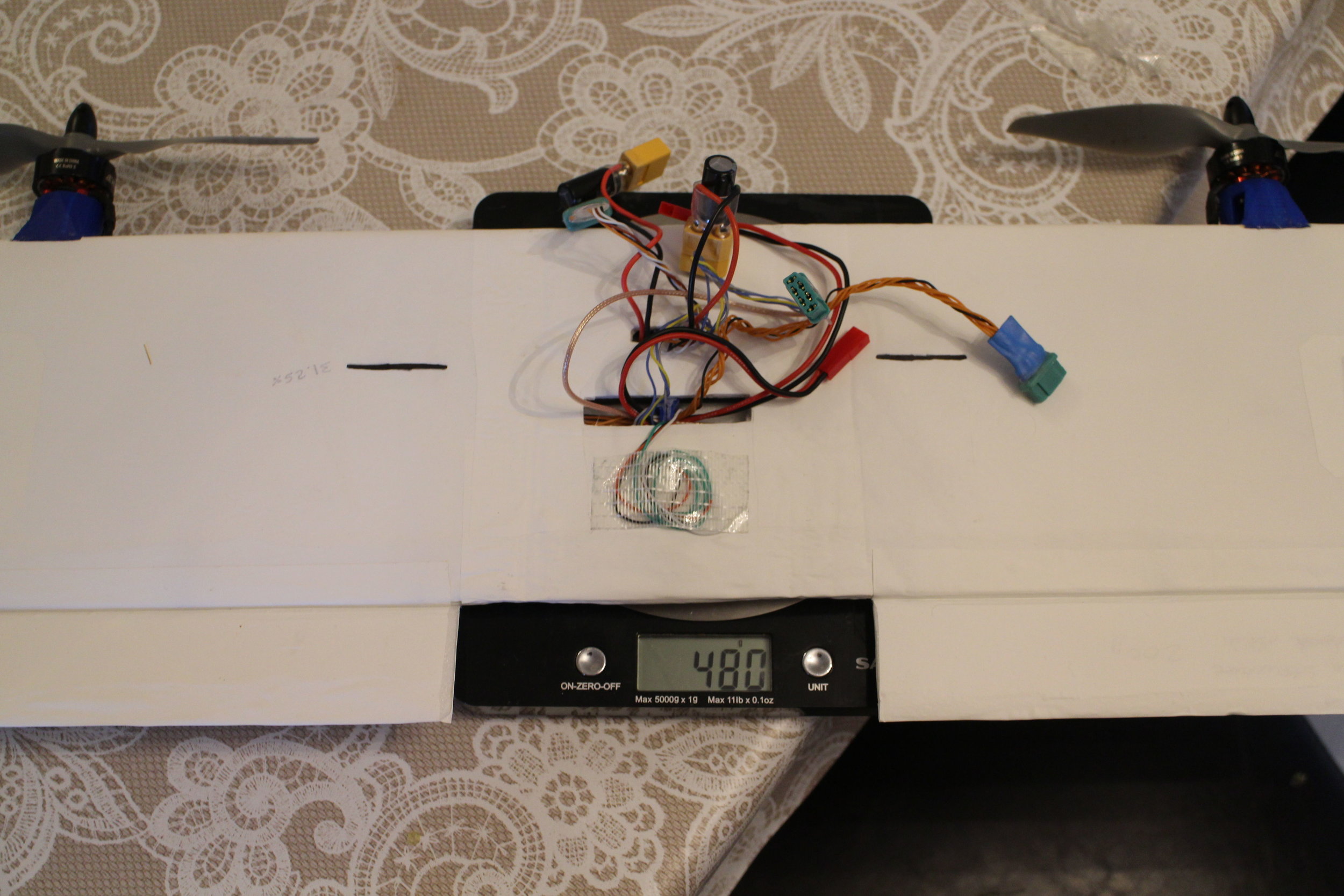
74g weight saving over the V1.5 wing with the new motors. This number seemed high to me, but I checked, and then checked again. 30g of that saving is the new covering film, and the only other significant difference is that the wingspan is 100mm shorter. I guess having 100mm less foam, 100mm less wire and so on save quite a bit overall? Certainly more that I thought. I was figuring the wing would weigh 40-50g less.
In all, the V2.0 weighs 107g less than the V1.5. This is a 10% weight saving, this is impressive alone, and is even more impressive when all of the additional strength is taken into consideration. The plane has 16% less wing area than the V1.5, but the 10% weight saving, together with the larger flaps, means the stall speed is aproximately the same.
This time the plane flew for a total of 66.5km in 1 hour and 28 minutes. Over this time the plane drew 10250mAh from my hybrid battery pack setup with 2x 3s 2200mAh Lithium Polymer batteries and 2x NCR 18650B 3s 3400mAh Lithium Ion Battery packs.
That gives an average current draw of 7.0 amps and an average efficiency of 154mAh/km.
Once I switch to my hybrid battery pack with 4x NCR 18650B 3s 3400mAh Lithium Ion Battery packs which would have a total capacity of 18000mAh and only weigh 300g more, I should immediately be up to 105km of range.
Compared to the timed flight that I did with the V1.5 plane, this is a very promising increase in performance and is about what I was expecting at that time.
Since the V1.5 however, I had also decided to cut down the wing span by 100mm and I designed a few improvements to reduce weight. These changes were both supposed to increase the efficiency on top of the efficiency gains already realised with the new motors, props and wingtips.
I’m guessing that reducing the wingspan actually reduced the efficiency and this was then cancelled out by the reduced weight, therefore keeping the efficiency the same overall. I was hoping that reducing the wingspan would reduce the parasitic drag more than it increased induced drag at cruise speed. It appears this was not the case. I will have to investigate further in the future.
Similar to before I have still not built a larger hybrid battery pack, but I do still believe that would increase range to around 105km while still being able to slow down to hand-catch speed. The propellers that I am using in this video were already a big improvement over the propellers used last time, but I will soon be trying some (I hope) even more efficient propellers.
I also had the same problem in this video as before with winds, the conditions were about the same of 10mph gusting 15.
My prediction this time around is that with all the mentioned improvements I could reach 140km of range.
Ambitious, but I believe possible.