
January 2019
Long Range Fpv Plane V1.0

I had many requirements and even more wants for this plane, and as always, everything is a compromise.
Things I Required:
Control Surface/Motor Setup That Allows for Electrical Dual Modular Redundancy Good Cruise Efficiency (< 100W at 60kph) Carry 1kg Payload (including batteries) Weigh Less Than 1kg Low Landing Speed (<20 kph) Large Fuselage for Payload Fit in My Car
Things I Wanted:
To Look Cool Be Hand Launchable AND Catchable Fly at Up to 120kph When Needed Affordable (good value) Be Easy to Repair Be Durable Fly Predictably
Comparison to existing products
There are a few planes that sort of meet these specs already in the RC FPV hobby, some examples of these are the X-UAV Mini Talon, the MFD Twin Dream (Multiplex Twinstar), the Ritewing Drak and the E-Flite Radian.
However, none of these meet all of my requirements, let alone my wants.

X-UAV Mini Talon

MFD Twin Dream

Ritewing Drak

E-Flite Radian
Pros: The Mini Talon has a good cruise speed of 50kph while consuming only around 60W of power, making it reasonably efficient for a plane of this weight, and more impressively, it does that with a low aspect ratio wing (AR=5.63). This allows it to be strong without any complex construction, making it easier to repair, and facilitates the implementation of the 2-piece wing, making it more compact. It also has a very large rectangular fuselage which is great for payloads.
Cons: Due to its layout, having one larger more efficient propeller at the back, the propeller creates a lot of noise running in the dirty air from the fuselage and the tail plane. This makes it much less friendly to fly ‘around’ people and means that it doesn’t have any power system redundancy. The latter is not too serious of an issue since modern electric power systems are extremely reliable, but I think I can do better. It weighs 1300grams and has a MTOW of around 1800grams, so it fails both of my weight requirements and the final problem with the Mini Talon is its stall speed, at 30-40 kph (depending on payload) it’s too high. The stall speed limits it to landing on perfectly flat surfaces with good approach angles, and completely rules out hand catching.
Pros: The Twin Dream has a large fuselage, and although it is not a nice rectangular shape it still has plenty of room for payload inside, it has twin motors mounted out on the wings allowing for some power system redundancy, but due to its small vertical stabiliser it is very unstable in single motor operation. It has a large 1800mm wingspan and 1.5 times the wing area of the mini talon, which allows it to slow down much more for landing and would get it close to hand-catch speed range. It weighs right around 1kg and has an MTOW of over 2kg, so is more than capable of carrying all the payload I would want.
Cons: Because of the larger wing area it has a cruise speed of around 40kph, while still drawing around 65W of power, this means that more of the payload capacity will be taken with batteries on longer range flights which is not ideal. The stall speed of around 25kph is still a bit higher than would be wanted, especially considering its low cruise speed, and since it does not have flaps it, like the mini talon, still needs a shallow approach angle. The biggest problem with the twin dream however is that it only has 1 servo controlling the pitch axis, and to make it worse, as standard it uses a 9 gram servo in a push-up configuration, which is just not appropriate for the stresses the servo will be put under. It also costs £200 just for the foam and laser cut plywood parts.
I’m generally not a big fan of the Ritewing Drak but considering how popular it is I feel it needs to be mentioned.
Pros: It has a very fast cruise speed of up to 100-120kph, while still only drawing 150W of power. This is achieved by having a very small wing area with a high wing loading, and by removing most of the fuselage and the tail plane. With full power (400W) it can fly at up to 150kph. Due to its small(er) size it can be transported more easily and because of its injection moulded EPP foam it has much more ‘handling’ durability and is much less likely to get damaged when being transported.
Cons: Naturally, with such a high cruise speed its stall speed is also very high at 60-70kph, as with the mini talon this limits it to only landing on perfectly flat surfaces with very shallow approach angles - completely unsuitable for what I want. Because of the very small fuselage it only has room for the batteries and no other payload. This is fine for many missions but vastly reduces its versatility. Furthermore, it has little to no redundancy having two servos, each shared between pitch and roll with an ‘elevon’ mix and since it is a flying wing it only has one motor. Also this motor is mounted behind the wing, in dirty air, making it very loud.
I am a very big fan of the E-Flite Radian (having owned 4 already), and so nearly used it for this project, even if heavily modified, but it has just too many downfalls.
Pros: On a good day the E-Flite radian can glide with the motor off indefinitely, this is very good from an efficiency standpoint because it would be able to cover large distances just hopping from thermal to thermal. On many occasions I have been able to keep it in the air for more than 6 hours with one 8Wh battery, only using power for the FPV, radio gear, and servos. It has a very slow cruise speed of 20-25kph but since it can stay in the air so long it can still cover large distances. Because it has such a low wing loading it can slow all the way down to 10-15kph, on a windy day this means it can land with zero ground speed! Despite its 2m wingspan it can be hand thrown and caught very easily making it unbelievably versatile and means that it can be flown from almost anywhere, no field needed at all. With a modified elevator it is also surprisingly manurable for a large, rudder-elevator glider, so it can tightly (and controllably) spiral into even the most compact areas, eliminating the problem of approach angles.
Cons: The Radian has many problems as a long range FPV platform. It requires lots of skill to constantly be finding thermals, it has no redundancy without modification, it has no ailerons as stock so it can’t be controlled by my autopilot, it weighs 700grams, but can only really carry 400 grams of payload, but worst of all is its low max speed of only around 35-40kph. It is limited to this by very severe flutter at higher speeds, but it doesn’t matter because it is so inefficient at these speeds anyway requiring 450W of power to maintain 35kph. That means that it would be horrendously easy to lose if caught downwind on a windy day. It also means that even short distance flights would take a very long time to complete. Unfortunately, that’s one characteristic that cannot be easily modified out of the plane, rendering it also unsuitable.
My Airframe Design Choices
After realising that there was no prebuilt solution for my situation (and just wanting to design something myself) I decided that I would have to build my own plane.
From the start I wanted to go with a built-up wing rather than a solid core, as this would allow me to put much more of the electronics in the wings, saving on wire length and the more valuable space in the fuselage. However, I also wanted to go with a predominantly foam construction since I already have lots of experience building and designing planes using house insulation foam, compared to the more traditional built-up wing structure using balsa wood and covering film.
I decided on 3mm foam wrapped around 3d printed wing ribs which would be glued to an 8mm main carbon spar in the inner section of the wing, and glued to a glass fibre spar in the outer sections (to save having carbon fibre near the antennas mounted at either wingtip).
In terms of the planform, I decided on a twin motor, high wing, V-tail, pod and boom style plane.
The twin wing mounted motors allow for power system redundancy while keeping prop noise low and keeping the props out of the image of the camera mounted on the fuselage. For efficiency I would prefer have one small backup motor and a primary motor with a larger, slower spinning propeller, but because they would both need to be on the centreline of the plane (such as the Cessna Skymaster) they would either get in the way of the camera view or be behind the plane making it noisy. In the future I may investigate a triple engine configuration.
The V-tail allows for pitch control redundancy without requiring an additional servo. Its not perfect, because if one v-tail servo fails, pitch control will be heavily coupled to yaw control, but this can be counteracted with the differential thrust from the twin motors.
Making it high wing keeps the wing mounted motors away from the ground, allowing the plane to take off and land on the ground without needing wheels which add weight and drag. The pod and boom tail design is similar in terms of drag to a conventional fuselage and is simple and lightweight.
I also decided on an un-swept un-tapered wing with an aspect ratio of AR = 10, wingspan of 1.6 metres and an MH32 Airfoil with a thickness of 8.75%. Aerodynamically I would prefer a higher aspect ratio and to have something like a 50% taper, with a straight leading edge giving a forward sweep, but what I decided on is the best compromise of structural and aerodynamic needs. Having an un-tapered wing also gives a more forgiving stall which is nice.
My power system design choices
I decided to use motors that are designed for racing quadcopters, they have an extremely high power to weight ratio and are surprisingly efficient. This makes them perfect for my use as I want to save as much weight as possible. I went with 1808 2400kv Multistar Motors from Hobby King as they are longer and narrower than most racing quadcopter motors meaning I can make a more aerodynamic pod for them.
I paired these motors with two 12A Electronic Speed Controllers from hobby king that are also designed for quadcopters, yet again they are very light weighing only 5grams each.
I’ll be running my power system directly from a hybrid 3 Cell Lithium polymer / 3 Cell Lithium Ion battery pack which I explain in greater detail here. This battery pack allows for long flight times due to the high energy density of the Lithium Ion cells, and high performance due to the low internal resistance of the Lithium Polymer cells.
I wasn’t sure exactly what propeller I would want to use, but since quadcopter propellers are so cheap I bought a large selection to test in flight.
My Control System Design Choices
The following design idea is largely what gave birth to this project, as it seemed like such a good idea I just had to try it out.
Normally when designing a redundant control system for an aircraft you might have two autopilots and one human pilot, you then have another device that checks that both autopilots are trying to do the same thing. If they are the action is carried out, if they are not then control is passed back to the human pilot.
This system doesn’t work so easily on a model aircraft and is very complicated to setup and get working correctly.
Instead in my design, the autopilot controls the left half of the aircrafts control surfaces (left aileron, left ruddervator) and the motors, and the human pilot controls the right half of the control surfaces (right aileron, right ruddervator).
When the autopilot is not in use it passes through the pilot’s commands to the motors and ‘its’ control surfaces, and the plane flies normally. When the autopilot is flying the plane, the pilot doesn’t need to move the sticks as the plane can fly fine only using the left aileron, left ruddervator and the motors. As explained earlier, the pitch control is coupled to yaw, but since the autopilot controls the motors it can compensate for that with differential thrust.
If the receiver (the pilot) fails the autopilot kicks in and returns the plane to home, the absolute worse case is that the receiver fails with its control surfaces fully deflected, in this case the autopilot would not be able to turn and would only be able to run in a straight line, and would probably crash, however this is a very unlikely failure mode (and not one that I have ever been able to create). In any situation better than this (such as a loss of radio link where the surfaces will return to centre) the autopilot will be able to return the plane home.
If the autopilot fails it will pass through the pilots controls and the pilot will be able to control the plane with all the control surfaces and the motors fly the plane normally. In the absolute worst case the autopilot will not passthrough the pilot’s control and will leave ‘its’ control surfaces at full deflection and the motors off. In this case the pilot would likely be able to travel in a straight line and turn/pitch in one direction allowing them to safely ‘crash land’ the plane, however, this is a very unlikely failure mode (and not one that I have ever been able to create). In any situation better than this (such as a loss of GPS signal) the pilot will be able to return the plane home.
This is not a perfect solution, but I think its about as good as you can get on an RC plane of this size and with this level of complexity, since this system provides nearly full redundancy with very little weight or complexity costs.
Also, with this control system either motor or any one servo can fail and the plane will be able to return home, again, as long as the servo doesn’t fail at full deflection, which is very unlikely and may still be recoverable.
For my autopilot I will be using a Matek F722 Wing flight control board running INav Autopilot software. This allows for many features such as return to home, 3d cruise, stabilised only and passthrough flight modes, a full on-screen display that shows home location, voltage, current, battery consumption, GPS height and speed and much more. I have also used it lots before so I’m already familiar with how it works.
For my radio link I will be using my modified FrSky Taranis transmitter (as detailed here) with an 868mhz R9M long range transmitting module and R9 Slim + receiver as my main link, with a FrSky X-Lite with a standard 2.4ghz transmitting module and Rx4R receiver as my backup link. All using my own antennas as described further here. This gives me both transmitter redundancy and frequency redundancy, but only at short range (<5 miles). This is however enough that if the radio link is lost far out, the autopilot can bring the plane back to within 5 miles and I can then takeover to do the landing.
My Video System Design Choices
For my video system I will have two cameras, one Foxeer Micro Arrow v3 mounted, fixed, on the tail and one Runcam Split Mini 2 mounted on a rotating and pivoting (pan and tilt) system on the front of the fuselage. The pan and tilt mount on the front will allow me to look around 360 degrees and up and down 120 degrees to look down at features on the ground for manually navigating or around, potentially to look for aircraft.
With a switch on my transmitter I’ll be able to switch between the cameras and between the main on-screen display and the secondary backup on screen display, which only shows essentials such as home position, battery voltage, speed and height.
All of this will be sent back to the pilot over a 5.8ghz analogue video link to my antenna tracking ground station which is further described here.
The video from the front pan tilt camera will also be saved onboard to a micro SD Card at 1080p 60fps.
Start of the build

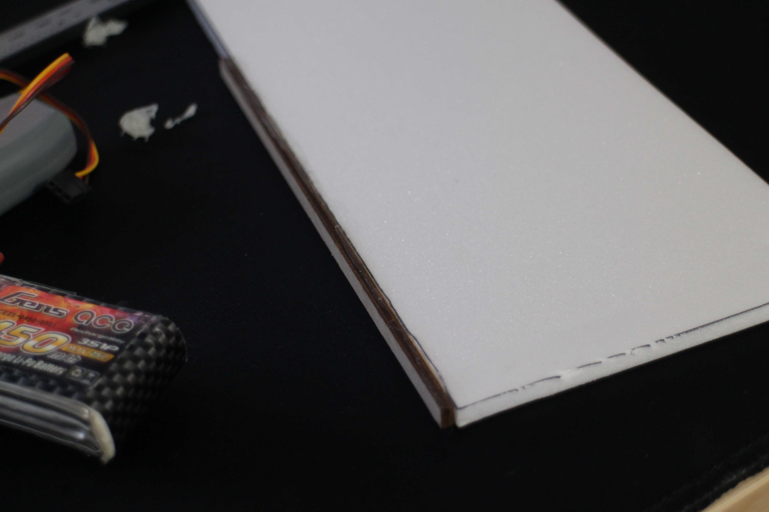
Build started by gluing the 3d printed wing ribs onto the main carbon spar with 2 part epoxy resin and then gluing that to the bottom wing skin to make the centre section of the wing.

Moutning the left outer wing section to the centre wing section showing the joint between the carbon wing spar and the radio signal friendly glass fibre spar.
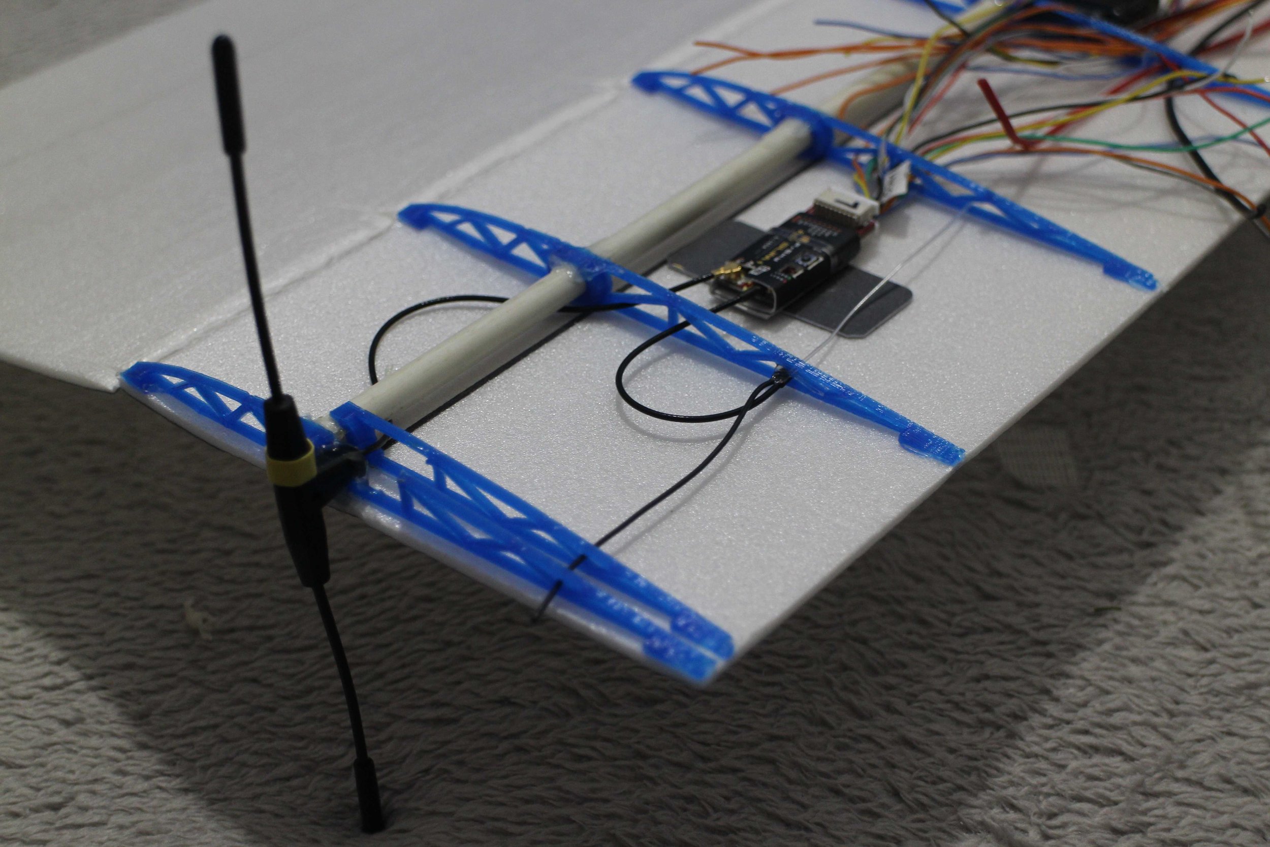
Main receiver mounted in the left wingtip with the two antennas mounted at 90 degrees to each other.

LM317T Voltage regulator set to 6V for the right aileron servo.

On the left is an LC filter to smooth the supply voltage going to the video transmitter, for cleaner video.

Receiver wires all connected up.

LED chip mocked up on the leading edge of the wing.

Working out how big I want the fuselage to be, using 2200mAh 3s LiPo batteries for reference.

Fuselage mostly glued together with an opening at the front for cooling air to pass through the fuselage, this may be covered up later, depending on compenent temperatures insdide the fuselage.

The centre section of the wing done with the original cables hanging out, these were later replaced for more compliant silicon cables.

View showing the internal structure of the centre section of the wing. Note the motor controllers mounted inside the wing between ribs in the centre.
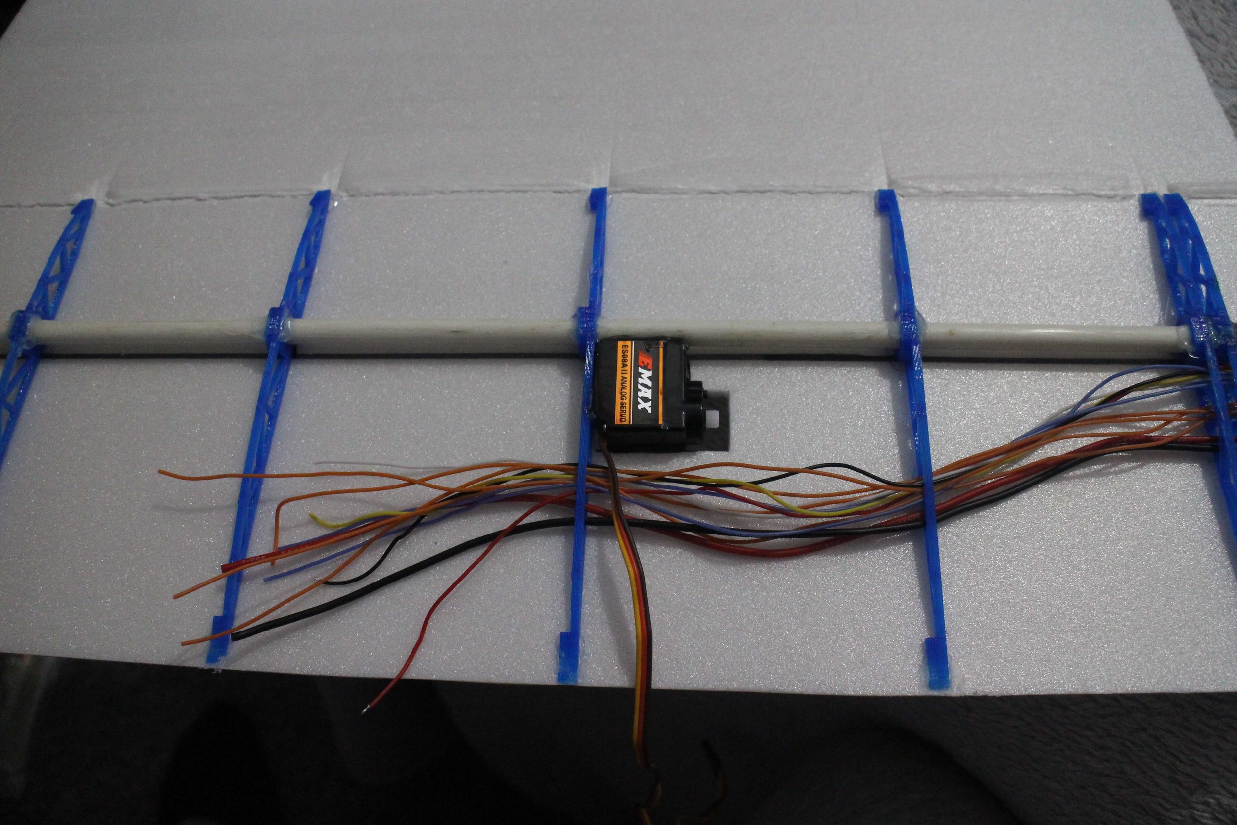
Emax ES08A ii Servo mounted in the outer left wing section, its glued directly to the main spar for extra rigidity. Also note the new silicon cables. 12 signal wires and 2 power wires go out to the receiver on the left wing.

AKK X2 Ultimate video transmitter being mounted flat with hot glue ouside the wing on the right wingtip. It is as far away as posible from the control receiver to limit interference and outside the wing for cooling.
Heatsink for the voltage regulator bent down into the airflow below the wing for cooling.

As always, joints in wires are spaced appropriately so that it doesn’t casue a large bulk in the wire, and reduces risk of shorts if the insulation fails. The joints are insulated with clear heat shrink for easier inspection.

3w LED Chips that I’ll be using for both navigation and strobe lights.

LED mounted interally makes the entire wing glow, aiding visibility.


Mounting of the tail boom into the fuselage.
3d printed V-tail Support piece.

Servo glued into place in one V-tail half.

Flaps on the bottom of the fuselage to acces the battery area.
Foam peices for tail with laser cut plywood strips glued into them for extra strength.

Both V-Tail halves.

Both V-Tail halves dry fitted in place with servos glued in place, this will come back to haunt me later.

Servo linkage to the ruddervator.

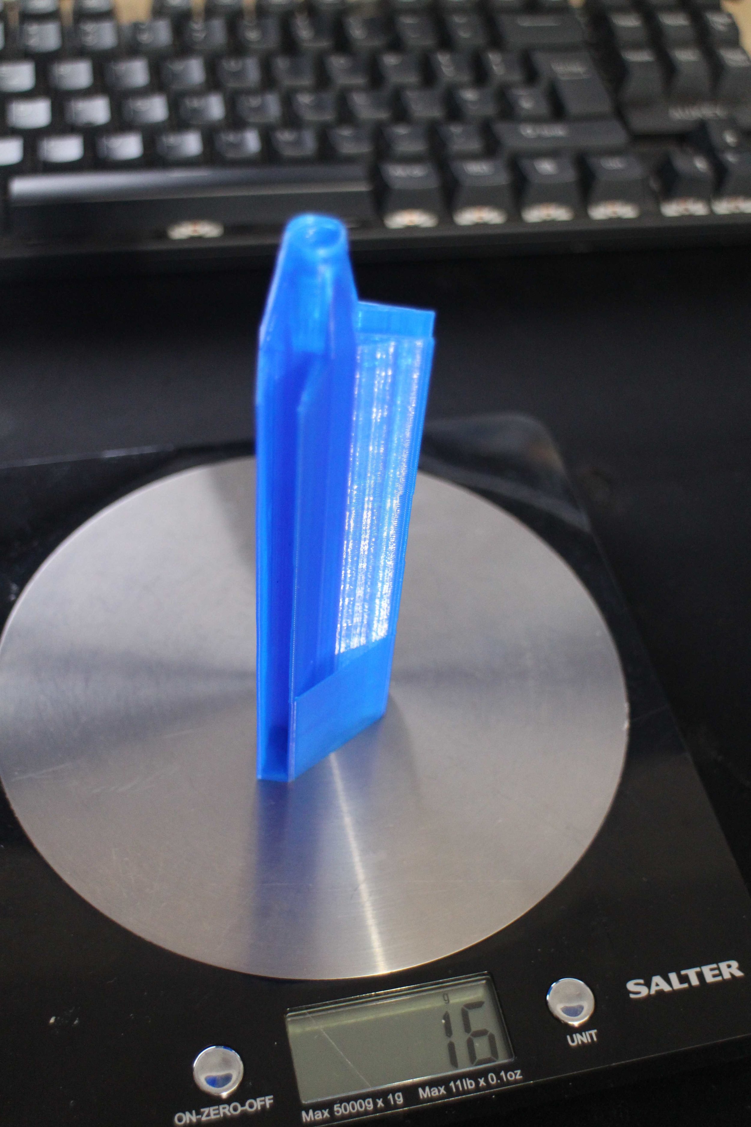
Comparing the weight of three Matek 5V Switching Voltage Regulators which are capable of a constant 2A to one LM317T Voltage regulator. (Three units are shown here to get a more accurate reading from the scales)
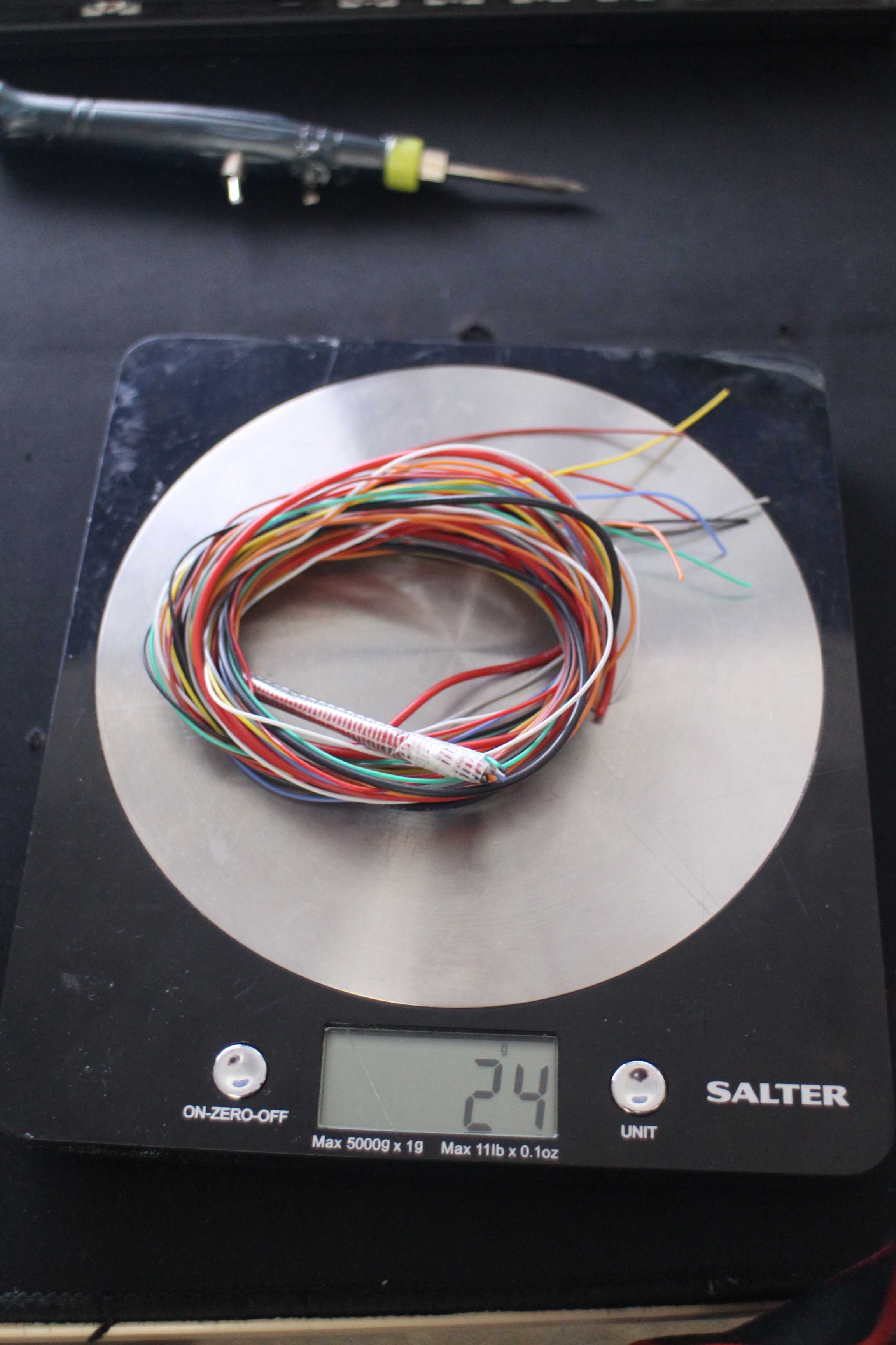
Weight of the 12 stands of 30awg and 2 strands of 18awg silcone wire that is run to the tail.

My first wiring harness between the wing and the fuselage, this is only for initial test flights since later I will be installing the autopilot.

Left outer wing section just before being glued together. Note the expanding glue along the front join to add strength to the leading edge to prevent handling damage.

The LM317T voltage regulator both weighs more, is less efficient and can only supply 1a, however since it is a linear regulator it doesn’t introduce switching noise, so I’m using it on the right wingtip near the video transmitter where I need a very clean power supply.

Wires exiting at the tail.

Tail servo voltage regulators mounted.

Wing rubber band tie downs mounted in the fuselage.

Right outer wing section before being glued together.
Aileron hinged using 3M Blenderm Tape. Note the beveling on the wing side of the joint that should have been done on the insde surface but I forgot to do it before gluing the wing together.


Battery placed in the battery bay.

All ready (or so I thought) for the first test flight.
Maiden Flight
Unfortunately, I didn’t get footage of the first flight since I didn’t have a camera person with me, my hat-cam was pointing way too high and I didn’t have an onboard camera since I didn’t want to damage more than I had to if the test flight went wrong. So I’ll explain it.
From the testing I had done before the flight it was evident that the plane was very overpowered with only one battery in it, as it was designed to be. It had a take-off weight of 700g including one 3s 2200mAh li-po battery and it had an estimated 1200g of thrust (enough to comfortably carry 1kg of payload). As I was hoping this made it a very fun plane to fly with only one battery.
With 75% throttle I let go of it, with barely any forward speed since it was so obviously wanting to get in the air, and it went almost straight up! It flew perfectly from the get go requiring very little trim to fly straight and level. I had the CG at 31% MAC and needed very little trim for changes in speed and was perfectly stable.
I flew for just over 2 minutes and then came into land and I immediately realised my mistake..

I had forgot to glue in the tail fins after I had dry fitted them a couple of weeks ago, luckily, the servo wire of all things was holding it in, otherwise the test flight may not have been so succesful. I got very lucky.
I glued them in properly and continued doing test flights.

After 20 flights the bottom of the fuselage is stil holding up fine to landings and takeoffs.
On the third test flight I started trying to push the planes speed capabilities, and at full throttle (which I now know to be around 115kph) I started to get aileron control reversal. Although I was not expecting it, this is something was already used to from previous projects, so I slowed the plane down and landed.
In most cases aileron control reversal is caused because when the aileron is deflected upwards to make that wing move down, the wing twists in the opposite direction increasing its AOA. The result is that the wing generates more lift instead of less and the wing moves upward, opposite of what was expected.
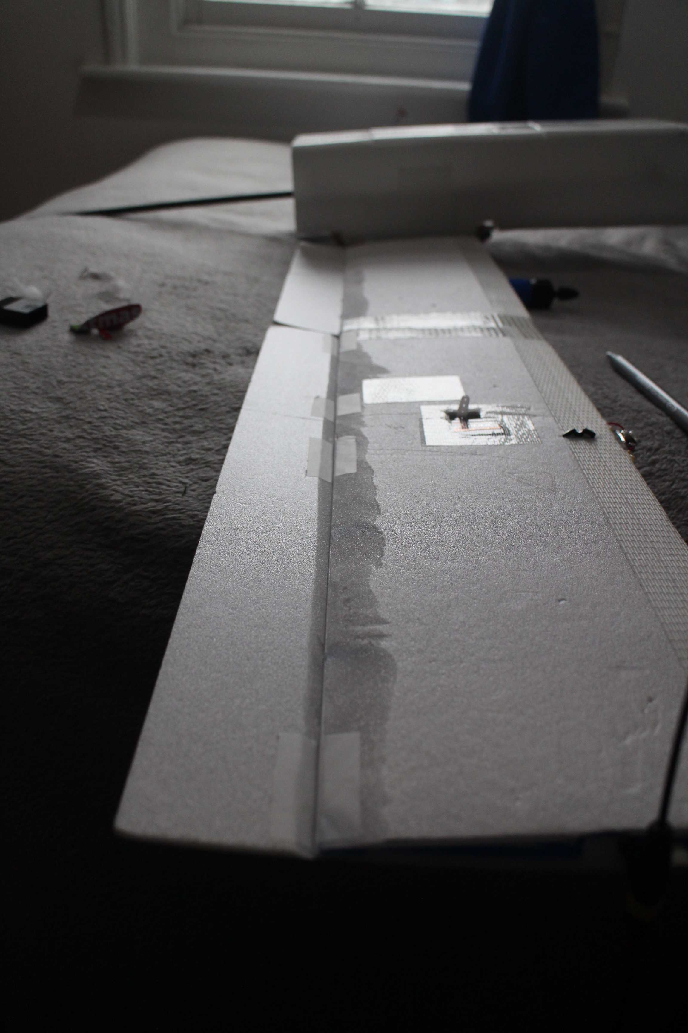
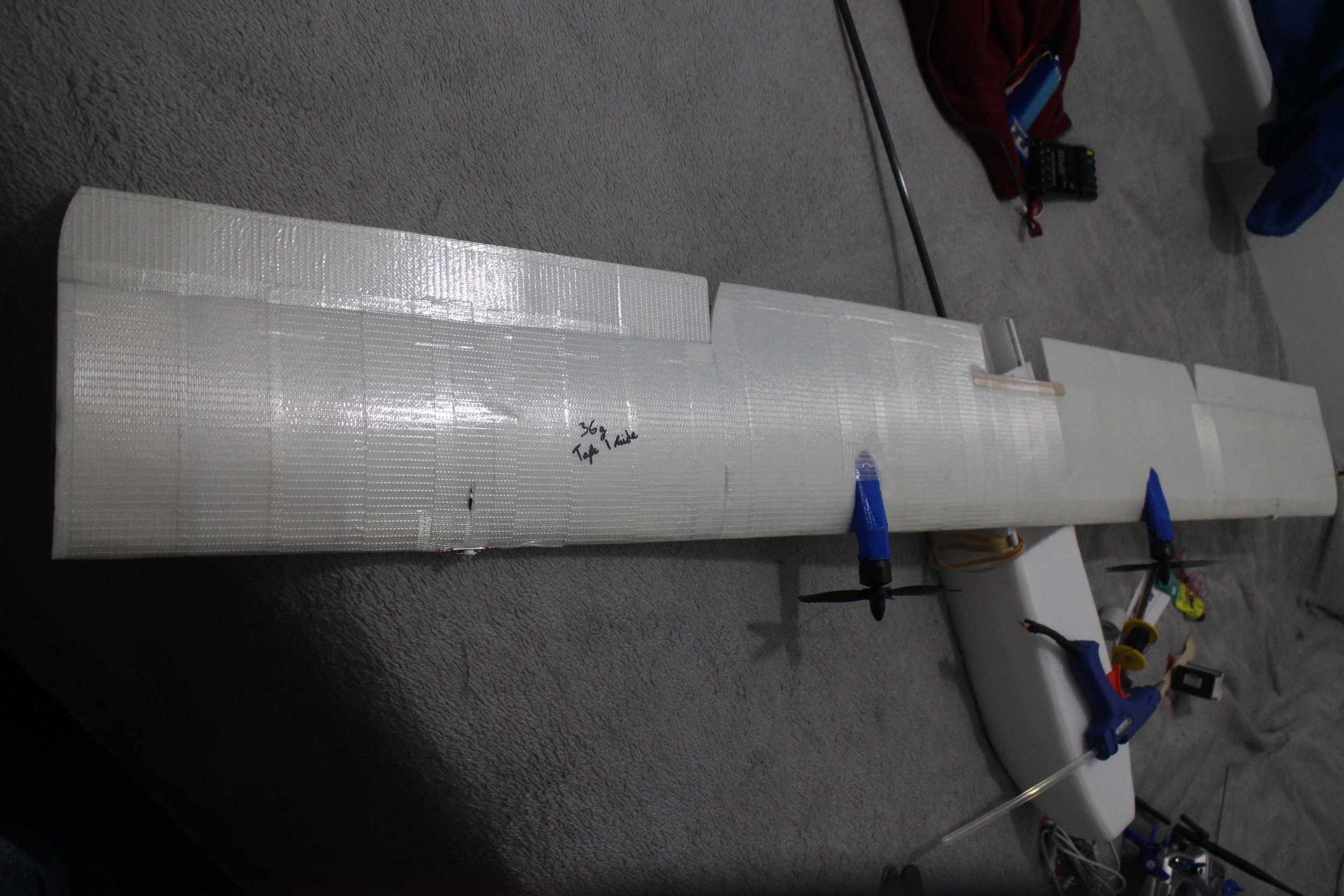
This was the case in this situation, to solve this problem I laminated the wing with 3M Glass Fibre Tape, this increased the torsional rigidity of the wing and stopped aileron control reversal at high speeds.
This was not the perfect solution however because it added 72g to the wing in total, that’s 10% of the weight of the entire plane! In the future I will have to investigate better laminating materials or a way to improve the torsional rigidity another way.
Unfortunately no audio, if you look carefully you can see the trail of smoke exiting the wing while landing.
So, I had an ESC fire midair while doing some aerobatics. This should have been obvious but I was being hopeful that it wouldn’t happen.
When I built the plane the ESC’s that I had bought didn’t arrive in time and I didn’t want to wait for them to arrive from china to close up the wing, so I put some ESCs that I already had in their place. The ESC’s that I had were rated for 12A continuous with ‘adequate cooling’, my motors draw a peak of 20A and they were embedded in house insulation foam. My justification for this was that I would only be using full power very infrequently since the plane has so much more power than It needs, and if I reached the 100W cruise efficiency that I wanted then each motor would be drawing < 5A continuous, which would be fine even with the ESC having no real cooling.
As it turned out this justification would have been completely fine, if I hadn’t got carried away doing aerobatics while flying with some friends.
Luckily by the time I blew up my 12A ESC the new 35A ESC’s had arrived. They are Flycolor X-Cross 35A ESC’s which are rated for 35A continuous with cooling so they should be more than adequate for 20A peaks.
The burnt ESC taken out of the wing.

New ESC ready to put in.
Both of the new ESC’s in place.

GPS for the autopilot mounted on the tail, as far away from the ‘noisy’ video transmitter, control receiver and motors as possible.

New wing connectors for the autopilot.
Cut a hatch in the wing for the receiver so that I could flash new firmware that had been released since I put it in the wing.
Some messy ceramic capacitors and an inline shottkey diode I added to the video transmitter power supply line to reduce a small amount of interference that was still left in the video downlink.
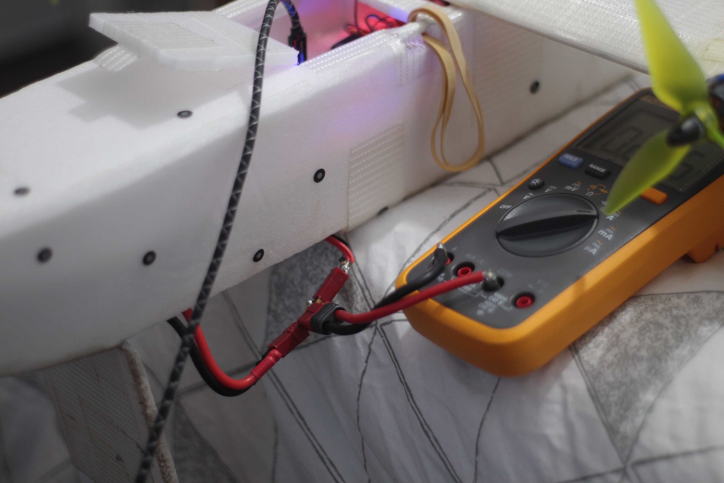
Calibrating the ammeter built into the flight controller.

Flight controller mounted in the fuselage and all wired up.
The Begining of V1.5
At this point I snapped the main wing spar ‘static load testing’ while showing the plane to my Dad, it broke more easily than I expected even if it was strong enough in flight. I realised that this was because my 3D printed wing ribs were creating pressure points on the pulltruded 8mm carbon fibre spar that I was using and that was something I had not predicted.


I was not particularly annonyed about this though since I had learnt lots in the first 30 or so flights on the plane and during the build and had lots of new ideas for how to build the new wing stronger, lighter, and with less drag.